Philips Hue – Great, only E27 ad GU10 lights?
Great system, but what about the E14 lights that I have around the house, and some others where the bulbs can’t be replaced with one of the Hue lights? It seems that the Osram Lightify Plug can be connected. A solution without soldering and flashing firmware would take the fun out of it. The new brand Innr offers a SmartPlug, that uses the Zigbee HA protocol. Could it also be used with the Zigbee ZLL protocol used by Hue? The answer is yes. It only requires flashing a custom firmware.
Custom firmware Hue lights
Credit goes to peeveeone who has been extremely persistent in figuring out how to connect his own lights to the Philips Hue. His breakthrough moment was when he found how to use a trust center link key. After that he was able to build a custom firmware for the NXP JN5168 Zigbee module. For this he used NXP example programs for smart lighting.
Without this work, I could never set out to hack the Innr SmartPlug.
Don’t try this at home
The author accepts no responsibility or liability for any adverse effects. This includes but is not limited to potential damage of the device itself, other equipment or personal harm, injury or dead. Working on electrical mains appliances can be dangerous. 230V is dangerous. If you decide to open such a device and work on it, never plug it into mains, until the device is closed again. If you do not feel comfortable with this, or want to experiment while powered with 230V: Do not proceed!
Innr SmartPlug Teardown
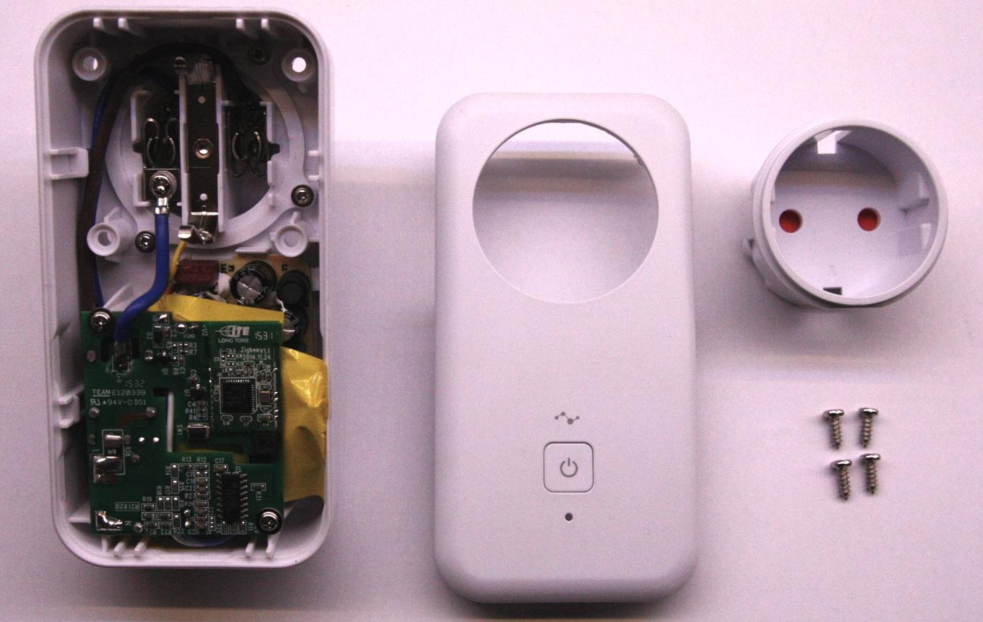
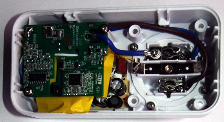
Opening starts with removing four screws at the rear side. Then separating the front from the case is the though part. At the top and bottom side, there are clips holding the front in place. the plastic is quite sturdy, so there is no other way then trying to squeeze it open at the top corners a bit with plastic wedges, and then just pull with force. When the cover is removed, the socket can be taken out.
It contains the NXP JN5168!
That is good news. It was an educated guess. Peeveeone was able to decipher the puzzle, because an Innr light bulb contained the same module, from which he was able to pull the firmware image. What is there more to see:
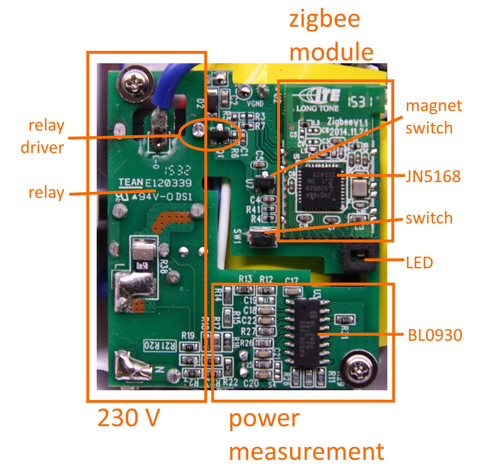
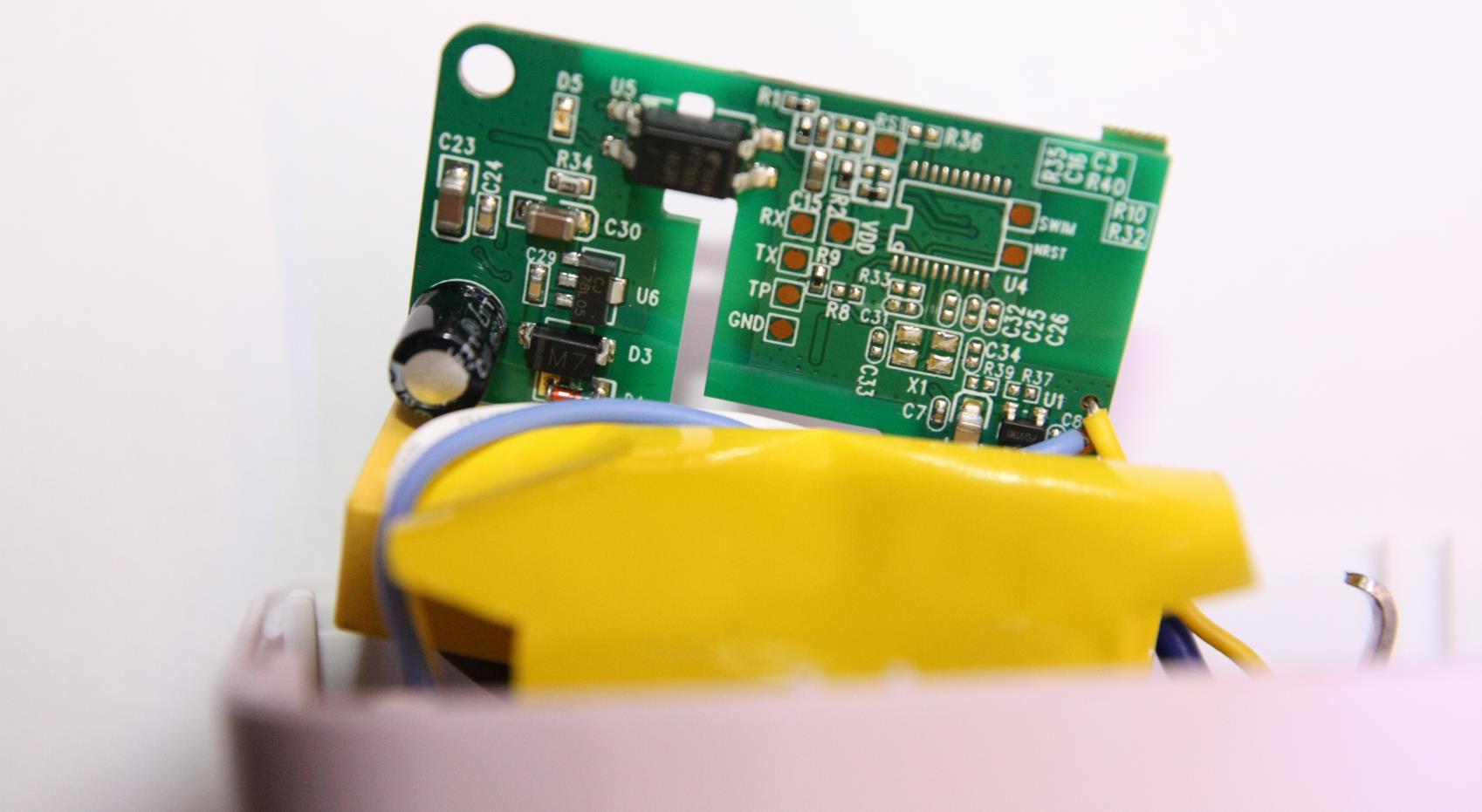
Basically there are three sections. The high-voltage section where a relay switches the 230V. A power metering section that probably is not very useful in a ZLL application. And finally the low-power (3.3V) section containing a JN5168 Zigbee/MCU module. At the rear side it can be seen that the power measuring section is galvanicly separated by an opto-coupler form the JN5168 section. There is a 5V-3.3V converter. Below the PCB there is a transformer which generates the 5V to power the low power section and the power measuring section:
The castellated JN5168 module soldered onto the main PCB has a remarkable resemblance with the NXP manufactured JN5168-001-M00. Lets compare them:
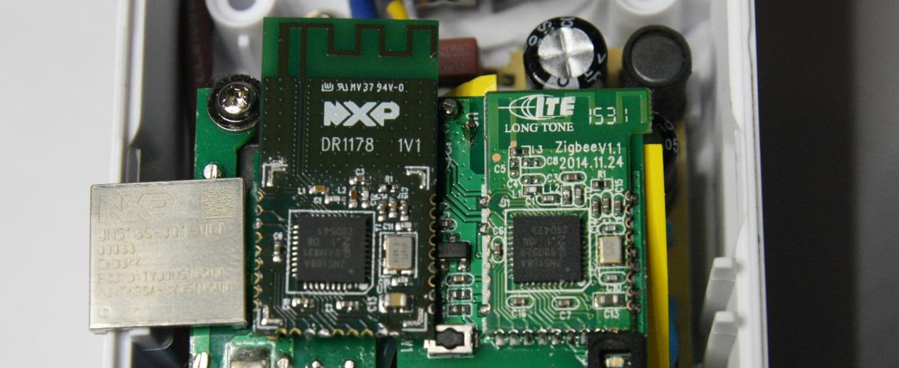
The resemblance is amazing. It is basically the same layout, to the level of most traces, capacitors and resistors. Only a tiny bit smaller. It already looks quite obvious, but a little bit of measuring around confirms that the castellated pins follow the pin assignments of the NXP module.
Probing the PCB revealed the following connections from the JN5168 module to the smartplug PCB:
| pin | name | smartplug function |
|---|---|---|
| 3 | DO1/SPIMISO | pull low to program |
| 12 | DIO6/TX | TX |
| 13 | DIO7/RX | RX |
| 14 | DIO8 | BL0930-p14 power metering |
| 15 | DIO9 | LED |
| 16 | DIO10 | Manual button |
| 17 | VDD | 3.3V |
| 18 | GND | GND |
| 20 | DIO12 | Relay |
| 22 | nRESET | pull low to reset |
| 23 | DIO14 | magnetic switch |
For the following pins I was not able to figure out the connection:
 1 - ADC1

 9 - DIO3

10 - DIO4

11 - DIO5

19 - DIO11

27 - VREF/ADC2
The remaining pins (2, 4, 5, 6, 7, 8, 21, 25, 25, 26) are not connected.
Hi, looking forward to your projects outcome and thanks for the hint about the debugging (I had it already set in the demo app but wasn’t thinking about it being disabled in the github rep from PeeVeeOne…).
I will keep my hands away from 230V and will be working with my 5V LEDs though.
On tuesday there will be a new post at my site as I successfully build the binary and to join my bridge. Now I can start with the real fun 😉
Regards, Boris