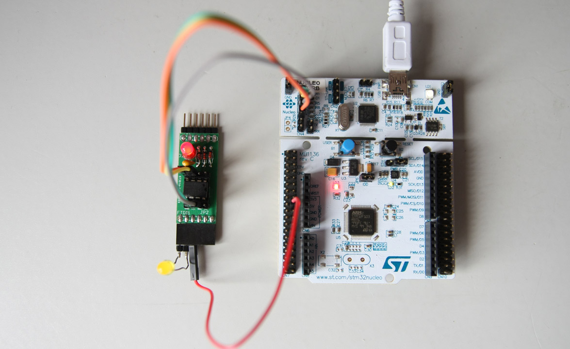
All LPC8xx microcontrollers have a SWD / JTAG interface for HW debugging. Even the tiny LPC810 has the SWD interface. Using it comes at a cost. A cost of two of the usable 6 pins. So there are still 4 remaining pins for your project! In this guide, the LPC810 SWD will be connected to the SWD interface of a competing brand demo boad. The Nucleo F103RB STM32 board. This board provides a on-board STLINK-V2-1 USB interface. Actually the board has two STM32 chips. One is the target of the demo board, and the other is the STLINK. This STLINK-V2-1 can be used as programmer and debugger for “external” targets. Even of foreign brands like NXP’s LPC-series. I am not the first to do similar things. In the reference some articles can be found that served as inspiration. The inexpensive nucleo boards can be obtained from companies like Farnell[5] and Conrad[6]
How to use the setup is described in article Picos ARM – HW debugger in Eclipse CDT.
Preparing the STLink Interface
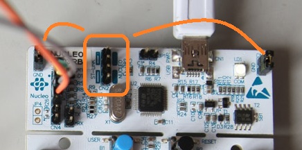 Remove the two jumpers from CN2, and place them at the two outermost empty jumper pins marked CN11 and CN12, as indicated by the orange box and lines. See also Figure 7, section 5.2.3 of ref [3].
This all there is to prepare the Nucleo STM32 for its STLink-V2-1 functionality.
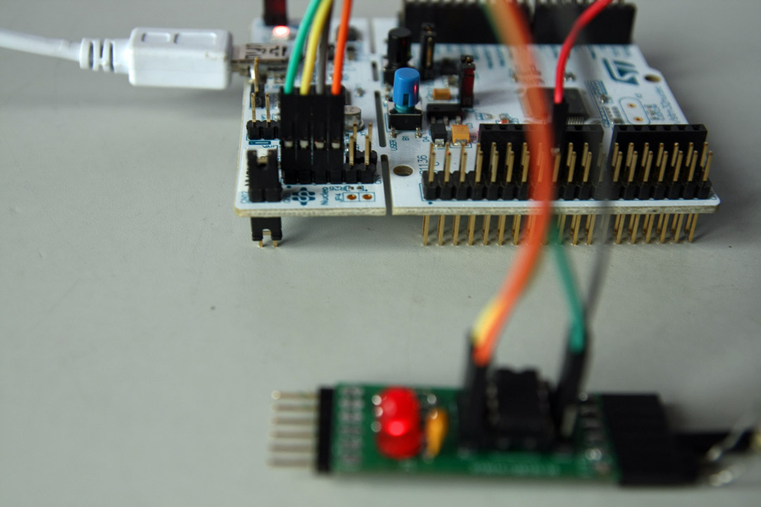
Connecting the SWD interface
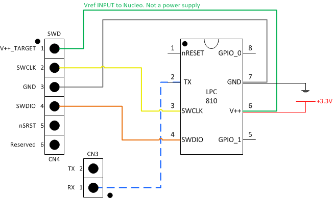 Connect according to the diagram. The green line is not a 3.3V power supply to the LPC810, but it informs the Nucleo SWD interface on the operating voltage of the target.
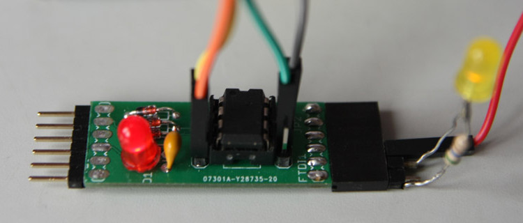
The LPC810 requires to be powered through another source (red wire).
SWCLK (yellow) and SWDIO (orange) are the actual debug signals.
Nucleo SWD nSRST remains unconnected.
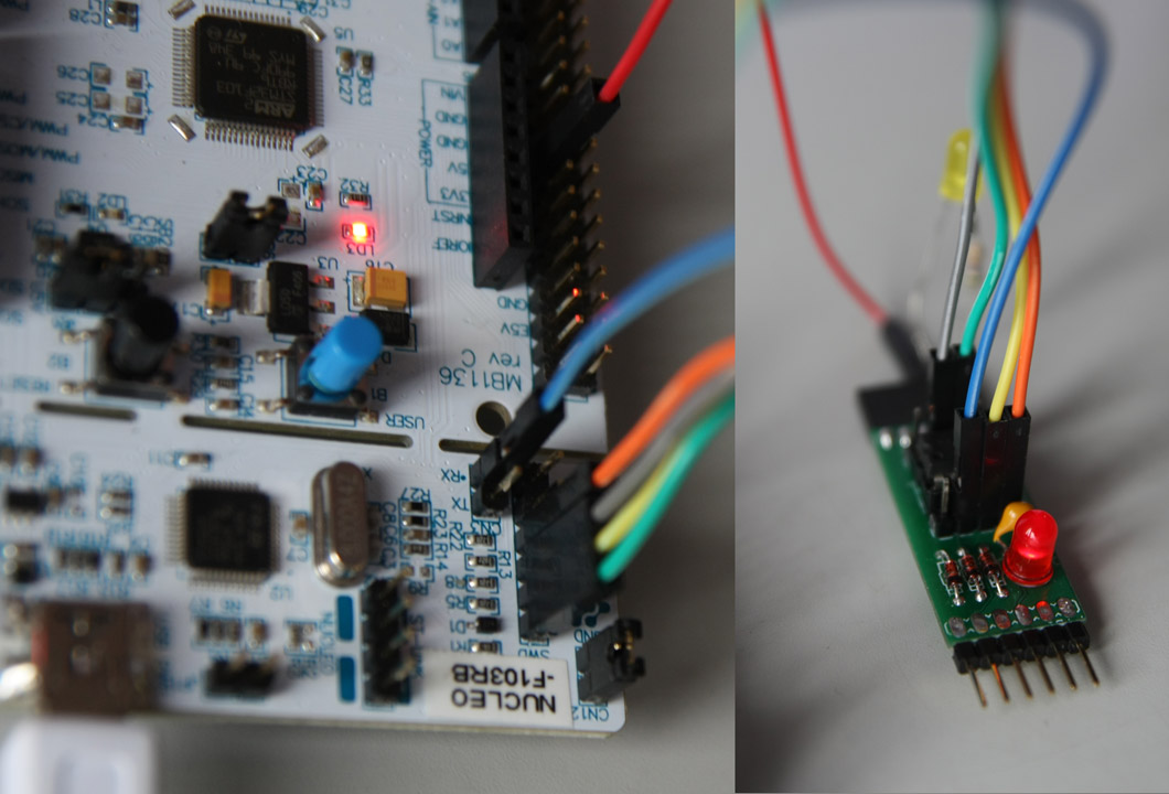
The Nucleo STM32 provides two lines for serial communication of the target. In this example the dashed blue line connects serial output of the LPC810 to the RX pin of the Nucloe STLink. The LPC810 can now print information on the console of the SerialUSB COM port of the Nucleo.
On the Nucleo and LPC810 the wires are connected like this:
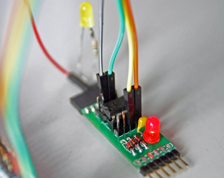
Connecting the Serial TX/RX interface
In this example pin 2 of the LPC810 is configured to be serial TX pin. The program running on the LPC810 can now print to console:
int main () {
    /* Pin Assign 8 bit Configuration */
    /* U0_TXD */
    LPC_SWM->PINASSIGN[0] = 0xffffff04UL; // only connect TXD

    /* Pin Assign 1 bit Configuration */
    /* SWCLK */
    /* SWDIO */
    /* RESET */
    LPC_SWM->PINENABLE0 = 0xffffffb3UL;

    uart0Init(115200);
    SysTick_Config(12000000/1000); // 1000 Hz
    printf("Hello from LPC%3x Blink\n", LPC_SYSCON->DEVICE_ID>>4);
}
Hi,
have you ever cutted off the STLINK/v2 from nucleo board?
If yes.
May you post me a connection / power schema to connect a standalone Nucleo Board wired to a Stlink/v2 board?
Than you
How do you connect another STM32 MCU with the st-link debugger