RFM69 OOK – DAGC, Sensitivity Boost and Modulation index

As a final step in exploring the optimal settings for receiving “foreign” OOK signals with the RFM69, the settings for DAGC, Sensitivity Boost and the effect of the Modulation index are explored. The modulation index is actually a FSK aspect, and no effect should be expected for OOK. However, as it can be programmed to High or Low, it is included in the exploration.

Foreign OOK refers to signals that are not natively produced by an RFM69, but are originating form various sensors or remote controls.

From the first results, it can be concluded that Sensitivity Boost has a clear advantage, and also DAGC enabled helps in icreasing sesnitivity:
RFM69SpecialModeHisto
Read More

RFM69 – Energy Count 3000 / ELV Cost Control

Conrad Energy Count 3000 and ELV Cost Control are wireles 230V electricity consumption measuring plugs Thomas Schulz has cracked the RF protocol of these device back in 2011 on the JeeLabs forum. The signals are FSK encoded and use the 868Mhz band. Thomas was able to receive them with a RFM12B module. Together with a JeeLink V3, it has found popular use with the German home automation software FEHM.

In this post I describe how the RFM69 can take over a task that earlier had to be performed in software.

One of the complications of the protocol is that the preamble of a series of 0x55 is scramble (whitened), and therefore more difficult to recognize. However, after scrambling it is still identical for all packets.

raw data 25 8A F9 59 DA 02 7E 15 ED 67 13 F1 85 D3 AC D2   [payload]   13 E6 84 A8 3B 
descramb 48 BB 55 55 55 55 55 55 55 55 55 55 55 55 55 7E   [payload]   7E 55 55 55 55 
               -------------------------------------- --   ---------   -- -----------
                             preamble                 HDLC  payload  HDLC  postamble

The original Jeelib-based RFM12B programs detection of valid packets was clumsy. Read More

RFM69 OOK compare antenna’s

The antenna design of a module like the RFM69 is important for the sensitivity to sognal and noise. Also antenna positioning is important. Putting an Nucleo STM32 with RFM69CW very close to a PC will result in a increase of several dBm’s in noise floor.

Gain 7 dB sensitivity with JeeNodes

The basic antenna design commonly used is a quarter wavelength wire antenna with ground plane.
quarterwavelengthantenna
From this informative paper from HopeRF, the manufacturer of the RFM69. Such an antenna has a 1/4 wavelength monopole, and a ground plane that serves to reflect (mirror) the wire so that one gets a half-wavelength dipole effect.

The 86mm wire (at 868MHz) connected to small JeeNode like devices is actually not having much of a ground plane. So this can probably be improved. There are very nice commercial designs for this at 868MHz and 433MHz. A.o from Conrad. So lets putthree 1/4 wavelength antenna’s to the test. The wire is compared to a home build and a commercial 1/4-wavelength with groundplane antenna. (See picture above this article, the blue wire crossing the Nucleo is the wire-antenna). Read More

RFM69 OOK RSSI and optimal bitrate

RFM69 OOK RSSI and optimal bitrate settings are key for proper reception and decoding of “foreign” OOK signals for example form remote controls as FS20, or wireless sensor such as Oregon scientific whether stations. In an earlier post, already some strange behavior of RSSI has been presented. A FS20 RC signal is recorded with 3 different bitrate settings in continuous OOK mode:

At high bitrates, the RSSI signal is much noisier. At 3000bps, the RSSI signal is hardly usable, although the internal bitslicer still can decode the signal, which has bit durations of 400 and 600us. So a too high bitrate will only lead excess noise.

From the 3000bps it can be seen that the RSSI signal is sampled with about 625us intervals. According to the datasheet, the RSSI sample duration depends on the duration of a bit:

t-rssi = 2 * t-bit

So for 3000bps, t-bit=333us, so t-rssi = 666us.
For 32768bps, the t-rssi=61us. As the RSSI signal is recorded with 25us intervals, most of the time two or three adjacent samples will have the same RSSI value.

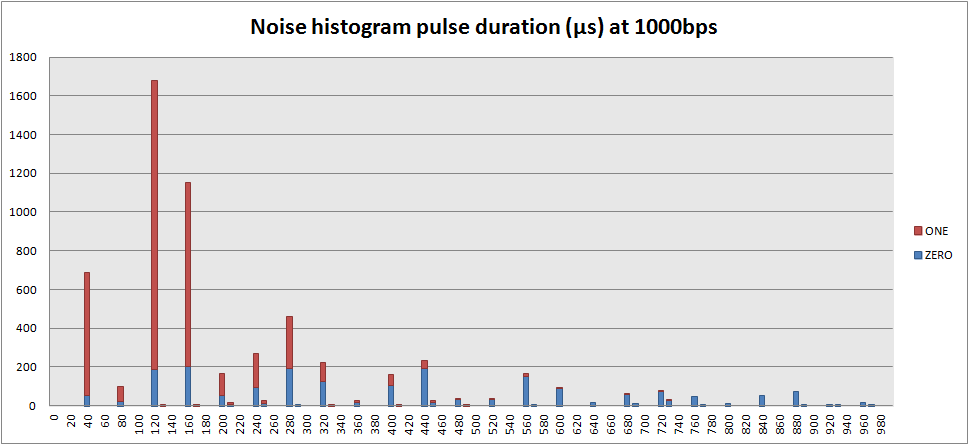
In an earlier post, it was explained that the internal bitslicer can slice at 1/25 of the bitrate. The fastest signals we want to see have bit duration (ON-time or OFF-time) of 200us (Some Oregon Scientific sensors). So then a low bitrate setting of around 1000bps will do?

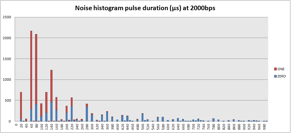
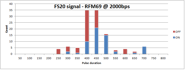
From further looking into exact timings or received signals, it appears that this is not true. When looking at a histogram of FS20 signals recorded with 2000bps, it can be seen that distributions of the 400us and 600us signals start overlapping. Also, the OFF-signals can be biased to shorter or longer durations, depending on the choice of OOK-PEAK or OOK-FIXED mode. As a result, the signal cannot be reliable decoded.

FS20 histo 2000bps

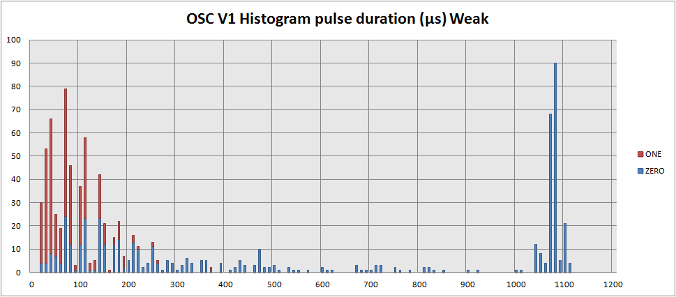
Now this is a bit messy. An ideal signal has both ON and OFF pulses taking either 400 or 600us:
FS20bit
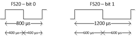
Deciding whether a bit is a zero or one, should simply testing whther the pusle duration is longer or shorter than 500us. Clearly that does not work. Also note it is an odd signal. It has many zero-bits, and only 11 one-bits.

When moving to a higher bitrate (32768bps), the variation on the bit-timing is greatly reduced, and it also appears that the timing is hardly dependent on the OOK-PEAK or OOK-FIX setting.

FS20 histo 32768bps

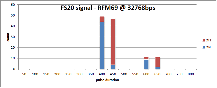
In conclusion, the bitrate should be high enough for reliable bit timings, but not higher then needed, as a lower bitrate means a better noise filtering.

Picos ARM – LPC8xx fun with Jeelabs on Windows

Picos ARM is a series of articles on this blog bringing the new LPC810 Jeelabs.org RFM69 activites described in the JeeBook to the Windows PC. For those who appreciate working with a comfortable full-blown IDE in stead of the Raspberry Pi command lines to build and debug stuff.

The series cover by now:

  1. Setting up an Eclipse IDE for LPC8xx projects in windows
  2. Flashing the firmware to the LPC8xx
  3. Setup of On-Chip Debugging in Eclipse IDE
  4. Connecting the Nucleo STLINK-V2-1 SWD debugger interface to the LPC810

Some Eclipse CDT Plug-ins have been developed to make setup and use of Eclipse IDE easier for the LPC8xx JeeBook type of projects. More will follow soon on easier setup of debugging facilities.

Evaluation noise filtering weak OOK signals – RFM69

As explained in a previous post , noise can spoil the reception of OOK signals from remote sensors. One solution to deal with the noise filtering of spikes in the ON/OFF binary signals is to apply a moving average filter of the last n received samples. When n is odd, the “average” is one if more then half the bits in the filter buffer is one, and otherwise zero. With a filter length of n=3 a single outlier sample will not disturb the intended signal. With a filter length of 5, spikes with a duration of two samples can be handled. Clean signals are as snappy as the where, and timings can be determined to the accuracy of the sample rate.

To find the optimal length of the moving average filter, a setup was created with a remote sensor giving a signal that was not received all the time. For each filter length, 100 transmissions where listened to. The graph below shows the success rate as function of the filter length.
433OOK_mov_avg_eval

The binary ON/OFF signal was sampled on the DATA/DIO2 pin of the RFM69 with sample rate 25µs. The bitrate was set to 4000bps. With this setting, the internal sampling rate of the RFM69 is 10µs. This “guarantees” a noisy signal for test purposes. The filter length n=1 is actually unfiltered data at 25µs/sample offered to the decoders. The longest filter length n=15 takes an averaging window of 375µs. This is resiliant to noisy spikes (either ON or OFF) of 7 times the sample rate, thus 175µs. The minimum pulse duration of the received signal, the Oregon Scientific V1 sensor, is about 1100µs, and obviously can stand the long filter periods.

For OOK signals that vary quicker, possibly a shorter filter length should be taken. The shortest pulse durations of OOK sensors and remote controls is around 300µs.

The design of the filter is simply an unbsigned integer, in which the most recent reading (1 or 0) is shifted in from the right. The filter length is enforced by only looking at the least significant n bits. Deciding on the filtered value is a matter of counting the one-bits in the filter.

//moving average buffer, max length = 31!
static uint32_t filter= 0;
static uint8_t avg_len = 7;
static uint32_t sig_mask = (1 << avg_len) - 1;

void receiveOOK() {
    while (....) {
        filter = (filter << 1) | (data_in & 0x01);

        //efficient bit count, from literature
        uint8_t c = 0;
        uint32_t v = filter & sig_mask;
        for (c = 0; v; c++)
        {
          v &= v - 1; // clear the least significant bit set
        }
        uint8_t data_out = (c > (avg_len >> 1)); //bit count moving average

        //decode OOK signal
    }
}

Debugging failure to detect OOK signals

For more remote OOK temperature sensors, occasionally transmissions arrive malformed, and can therefore not be detected as such or properly decoded. The Oregon Scientific THN128 protocol V1 sensor perfoms two transmissions spaced some 200ms apart. When the first transmission is received properly, it is easy to record the raw RSSI and OOK data from a RFM69 during the transmission of the repeated signal. I have recorded two of the transmissions where the first part was succesful, and the second part contained an error.

The errors are in the marked area’s. It appears that such a bit-error is a noise spike that only takes one sample in both cases. Although it is a bit early to proof, it is very likely that failures to detect weak OOK signals are often short time-scale (high frequency) noise on the OOK signal.

Noise

Recording a histogram of all ON and OFF durations of the second transmission, including the preceeding gap after the end of the first transmission gives better insight in the high frequency noise.
rfm69_ook_oscv1_pulse_dur_histo_4000bps_n10

The OFF (ZERO) peak at 1080µs belongs to the received OOK signal. The large distribution at the left hand side of the graph is noise. The red part indicate signal ON (ONE), and tend to be short between 40 and 100µs. For the OFF state the noise tail is a bit longer. It is clear that most noise energy is below the 200µs tiem-scale. Most remote control and sensor OOK pulse durations are above the 300µs time scale, so it should be possible to filter out the high frequency ON/OFF flips to clean-up the signal.

Filtering

So could the reception be improved by getting rid of this type of short spikes on the intended signal? I have been thinking about this. When not using an interupt driven approach to detect ON to OFF and OFF to ON transitions, but by just polling the DATA (DIO2) pin of the RFM69, I can easily implement a kind of moving average filter for the two-valued data. Sampling at for exmaple 40µs and averaging the last 5 samples removes spikes of one and two sample duration. I tested this and it improves the reception of weak signals way better then I expected. I am now collecting more data on the improved performance.

RFM69 OOK internal sampling rate

When the RFM69 is used in continuous OOK mode, the signal can be read from the RFM69 DATA (DIO2) pin. This can be done by polling this line with an ardiuno, jeenode, nucleo STM32 or other MCU. It can also be done interrupt driven by programming interrupts on the rasing and falling edge of the DATA signal. This way accurate timings can be measured. On the nucleo STM32 F103RB with ChibiOS I can measure pulse lengths of OOK signals with an accuracy of one or two microseconds.

I decided to generate some OOK signal (and only noise) histograms to figure out how to deal with some high frequency noise in the OOK signals. I set the OOK bitrate in the RFM to 1000bps as the pulse durations are in the order of one millisecond in the signals I was working with. Then I found that pulse durations I measured were quite discrete. A saw peaks around 40µs, 80µs, etc. Further experimentation revealed that this discretisation internally in the RFM69 depends on the bitrate. With a bitrate of 2000, the peaks occured at 20µs intervals. So I concluded that the internal sampling of OOK signals happens at 25 times the anticipated bitrate (chiprate). More aquirate measurements are required to detemrine the exact periodicity. It could also be 24 times or something like that.

Below are two histograms where the bin size is 10µs, recorded for 30 seconds, with 1000 and 2000 bps.

rfm69_ook_noise_pulse_dur_histo_2000bps

rfm69_ook_noise_pulse_dur_histo_1000bpsIt can be clearly seen that with the lower bitrate also the measured noisy ONES (ON) and ZEORS (OFF) are detected at the 40µs., leaving three bins (nearly) empty in between. With longer durations it can be seen that the mismatch with the 40µs grid slightly increases. This can be due to either the factor of 25 not being accurate, but more likely it can be a mismatch between the RFM69 crystal clock and the nucleo internal oscillator, leading to slight clock differences between the two components.

Conclusion

Internally the RFM69 samples the RSSI at 25 times the programmed bitrate to detect ON or OFF OOK signal. This knowledge can be useful in figuring out the optimal OOK settings for reception of different OOK signals in various formats and bitrates. For example when using one reciever for a light switch control system such as KAKU and Oregon Scientific temerature sensors.

RFM69 Bandwidth investigations part 1

Usually there are several 433MHz devices around the house. Remote controls and various sensors. Normally the exact operating frequency is notknown. A lot of work described on the internet is done with wide-band receivers. The following graphs show the relation between the receiver bandwidth and the bandwidth of the received signal.

Frequency sweeps of continuous OOK transmission with different receiver bandwidth settings. The graphs show the variance on the sampled RSSI signal.

A rule of thumb is that the sweep is performed with the RFM69 receiver OOK-bandwidth being equal to the frequency step size of the sweep. This gives about 3 datapoints with elevated variance, providing good view to estimate the the peak frequency (433.81MHz for the KAKU remote)First a coarse sweep with steps of 100kHz can be perfoemd, followed by a narrow sweep with step size of 5 or 10kHz.