The antenna design of a module like the RFM69 is important for the sensitivity to sognal and noise. Also antenna positioning is important. Putting an Nucleo STM32 with RFM69CW very close to a PC will result in a increase of several dBm’s in noise floor.
Gain 7 dB sensitivity with JeeNodes
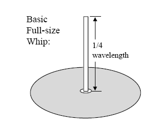
The basic antenna design commonly used is a quarter wavelength wire antenna with ground plane.
From this informative paper from HopeRF, the manufacturer of the RFM69. Such an antenna has a 1/4 wavelength monopole, and a ground plane that serves to reflect (mirror) the wire so that one gets a half-wavelength dipole effect.
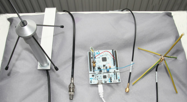
The 86mm wire (at 868MHz) connected to small JeeNode like devices is actually not having much of a ground plane. So this can probably be improved. There are very nice commercial designs for this at 868MHz and 433MHz. A.o from Conrad. So lets putthree 1/4 wavelength antenna’s to the test. The wire is compared to a home build and a commercial 1/4-wavelength with groundplane antenna. (See picture above this article, the blue wire crossing the Nucleo is the wire-antenna). Read More
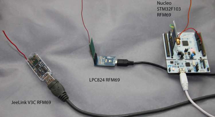
The RFM69 contains internal calibration features for the receive circuitry. So in theory different RFM69 receivers should have comparable noise levels as well as comparable signal levels provided the antenna design is the same, and also the antenna positioning is comparable for the receivers. Now lets put this theory to the test. Read More
RFM69 OOK RSSI and optimal bitrate settings are key for proper reception and decoding of “foreign” OOK signals for example form remote controls as FS20, or wireless sensor such as Oregon scientific whether stations. In an earlier post, already some strange behavior of RSSI has been presented. A FS20 RC signal is recorded with 3 different bitrate settings in continuous OOK mode:
At high bitrates, the RSSI signal is much noisier. At 3000bps, the RSSI signal is hardly usable, although the internal bitslicer still can decode the signal, which has bit durations of 400 and 600us. So a too high bitrate will only lead excess noise.
From the 3000bps it can be seen that the RSSI signal is sampled with about 625us intervals. According to the datasheet, the RSSI sample duration depends on the duration of a bit:
t-rssi = 2 * t-bit
So for 3000bps, t-bit=333us, so t-rssi = 666us.
For 32768bps, the t-rssi=61us. As the RSSI signal is recorded with 25us intervals, most of the time two or three adjacent samples will have the same RSSI value.
In an earlier post, it was explained that the internal bitslicer can slice at 1/25 of the bitrate. The fastest signals we want to see have bit duration (ON-time or OFF-time) of 200us (Some Oregon Scientific sensors). So then a low bitrate setting of around 1000bps will do?
From further looking into exact timings or received signals, it appears that this is not true. When looking at a histogram of FS20 signals recorded with 2000bps, it can be seen that distributions of the 400us and 600us signals start overlapping. Also, the OFF-signals can be biased to shorter or longer durations, depending on the choice of OOK-PEAK or OOK-FIXED mode. As a result, the signal cannot be reliable decoded.
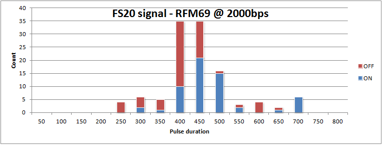
Now this is a bit messy. An ideal signal has both ON and OFF pulses taking either 400 or 600us:
Deciding whether a bit is a zero or one, should simply testing whther the pusle duration is longer or shorter than 500us. Clearly that does not work. Also note it is an odd signal. It has many zero-bits, and only 11 one-bits.
When moving to a higher bitrate (32768bps), the variation on the bit-timing is greatly reduced, and it also appears that the timing is hardly dependent on the OOK-PEAK or OOK-FIX setting.
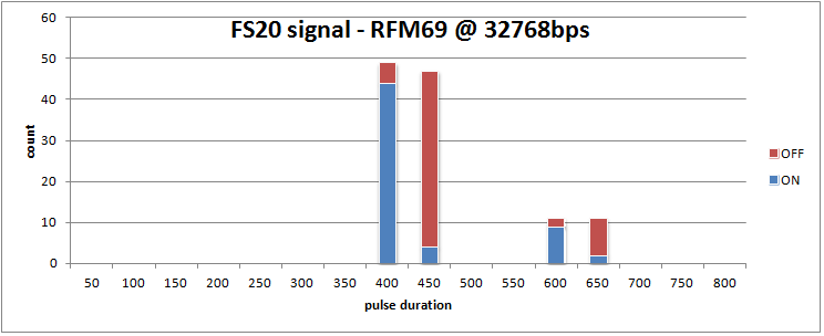
In conclusion, the bitrate should be high enough for reliable bit timings, but not higher then needed, as a lower bitrate means a better noise filtering.
As explained in a previous post , noise can spoil the reception of OOK signals from remote sensors. One solution to deal with the noise filtering of spikes in the ON/OFF binary signals is to apply a moving average filter of the last n received samples. When n is odd, the “average” is one if more then half the bits in the filter buffer is one, and otherwise zero. With a filter length of n=3 a single outlier sample will not disturb the intended signal. With a filter length of 5, spikes with a duration of two samples can be handled. Clean signals are as snappy as the where, and timings can be determined to the accuracy of the sample rate.
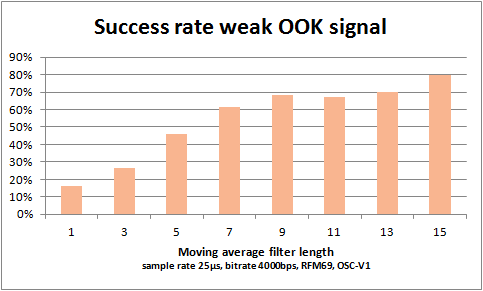
To find the optimal length of the moving average filter, a setup was created with a remote sensor giving a signal that was not received all the time. For each filter length, 100 transmissions where listened to. The graph below shows the success rate as function of the filter length.
The binary ON/OFF signal was sampled on the DATA/DIO2 pin of the RFM69 with sample rate 25µs. The bitrate was set to 4000bps. With this setting, the internal sampling rate of the RFM69 is 10µs. This “guarantees” a noisy signal for test purposes. The filter length n=1 is actually unfiltered data at 25µs/sample offered to the decoders. The longest filter length n=15 takes an averaging window of 375µs. This is resiliant to noisy spikes (either ON or OFF) of 7 times the sample rate, thus 175µs. The minimum pulse duration of the received signal, the Oregon Scientific V1 sensor, is about 1100µs, and obviously can stand the long filter periods.
For OOK signals that vary quicker, possibly a shorter filter length should be taken. The shortest pulse durations of OOK sensors and remote controls is around 300µs.
The design of the filter is simply an unbsigned integer, in which the most recent reading (1 or 0) is shifted in from the right. The filter length is enforced by only looking at the least significant n bits. Deciding on the filtered value is a matter of counting the one-bits in the filter.
//moving average buffer, max length = 31!
static uint32_t filter= 0;
static uint8_t avg_len = 7;
static uint32_t sig_mask = (1 << avg_len) - 1;
void receiveOOK() {
while (....) {
filter = (filter << 1) | (data_in & 0x01);
//efficient bit count, from literature
uint8_t c = 0;
uint32_t v = filter & sig_mask;
for (c = 0; v; c++)
{
v &= v - 1; // clear the least significant bit set
}
uint8_t data_out = (c > (avg_len >> 1)); //bit count moving average
//decode OOK signal
}
}
When the RFM69 is used in continuous OOK mode, the signal can be read from the RFM69 DATA (DIO2) pin. This can be done by polling this line with an ardiuno, jeenode, nucleo STM32 or other MCU. It can also be done interrupt driven by programming interrupts on the rasing and falling edge of the DATA signal. This way accurate timings can be measured. On the nucleo STM32 F103RB with ChibiOS I can measure pulse lengths of OOK signals with an accuracy of one or two microseconds.
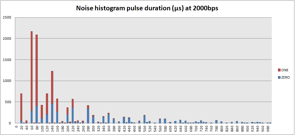
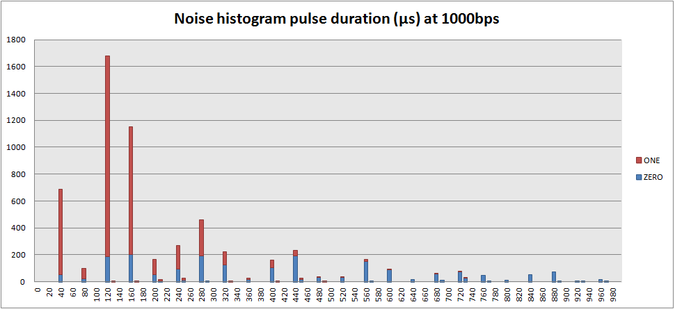
I decided to generate some OOK signal (and only noise) histograms to figure out how to deal with some high frequency noise in the OOK signals. I set the OOK bitrate in the RFM to 1000bps as the pulse durations are in the order of one millisecond in the signals I was working with. Then I found that pulse durations I measured were quite discrete. A saw peaks around 40µs, 80µs, etc. Further experimentation revealed that this discretisation internally in the RFM69 depends on the bitrate. With a bitrate of 2000, the peaks occured at 20µs intervals. So I concluded that the internal sampling of OOK signals happens at 25 times the anticipated bitrate (chiprate). More aquirate measurements are required to detemrine the exact periodicity. It could also be 24 times or something like that.
Below are two histograms where the bin size is 10µs, recorded for 30 seconds, with 1000 and 2000 bps.
It can be clearly seen that with the lower bitrate also the measured noisy ONES (ON) and ZEORS (OFF) are detected at the 40µs., leaving three bins (nearly) empty in between. With longer durations it can be seen that the mismatch with the 40µs grid slightly increases. This can be due to either the factor of 25 not being accurate, but more likely it can be a mismatch between the RFM69 crystal clock and the nucleo internal oscillator, leading to slight clock differences between the two components.
Conclusion
Internally the RFM69 samples the RSSI at 25 times the programmed bitrate to detect ON or OFF OOK signal. This knowledge can be useful in figuring out the optimal OOK settings for reception of different OOK signals in various formats and bitrates. For example when using one reciever for a light switch control system such as KAKU and Oregon Scientific temerature sensors.
With the RFM69 in continuous FSK mode, polling the RSSI register at sufficient rate can be used to acquire OOK signals like on oscilloscope. However when doing so with receiver mode set to OOK, it becomes clear that the RSSI register is used internally for some other purposes:
The following table shows the differences in intialisations of the RFM12B for the JeeNode applicaiton to receiver weather station data from both FSK and OOK stations, and send it to the JeeNode home sensor network, and eventually to HouseMon:
JeeLib native
WH1080 FSK
JeeLib OOK
Jeelib native remark
WH1080 FSK Remark
JeeLib OOK
0x8205
0x820D
disable some circuits
0x80E7
0x80E7
868 Mhz, enable tx+rx
identical
disable TX and RX buf
0xA640
0xA67C
0xA68A
frequency
0xC613
0xC613
0xC691
bitrate
N/A ?
0x94A2
0x94A0
0x9489
134kHz, -0dBm, 91dBm
134kHz, -0dB, 103dBm
200khz, -6db, 97dbm
0xC2AC
0xC220
datafilter = digital
datafilter = OOK
0xCA83
0xCA83
0xCA00
identical
FIFO disabled
0xCEnn
0xCED4
group ID
groupID=0xD4!
0xC483
0xC49F
0xC473
AFC auto, free, DQD4
AFC manual slow +-16 DQD2
AFC @PWR, auto, +-4 DQD4
0x9850
0xCC77
0xCC67
0xCC67
PLL don't care
PLL don't care
0xE000
0xE105
wakeup timer
don't care
0xC800
0xC80E
0xC800
disable low duty cycle
0xC049
0xC006
0xC040
clock out, low batt level
don't care
don't care
0XB800
0XB800
clear transmit buffer
0x82DD
0x82DD
0x82C0
enable relevant circuits
identical
enab receiver, baseband
taking a look at the differences between the native-FSK and WH1080-foreign-FSK, there seem to be some obvious required differences, but also some differences that may not matter that much. For example the auto frequency control (AFC) settings, auto-mode, unrestricted, versus manual, slow, restricted to +/-16steps may not a big deal. So I tested this by making a sketch that receives foreign-FSK, and as soon as a signal is received, it programs the RFM12B to native mode and transmits the package into the sensor network. I extended the RF12 driver with functions below, which speak for themselves. The minimal set of changes can be seen in the following functions:
void configureWH1080 () {
rf12_setGroup(0xD4);
rf12_setBitrate(0x13); // 17.24 kbps
rf12_setFrequency(0x67C); // 868.300 MHz
rf12_setFixedLength(LEN_MAX); // receive fixed number of bytes
}
void deconfigureWH1080 () {
rf12_setGroup(GROUP_ID);
rf12_setBitrate(0x06); // 49.2 kbps
rf12_setFrequency(0x640); // 868.000MHz
rf12_setFixedLength(0); // number of bytes to be received in packet header
}
This approach avoids using the slightly costly rf12_initialize() funnction which reprograms the SPI bus and resets the RFM12B.
If you made it to here, but think what is this all about. See this:
Using an Arduino, JeeNode, Nodo, or Raspberry Pi with RFM12B, RFM01 or superheterodyne receiver, sensors of popular wireless consumer weather stations can be received. Your own, or your neighbors. This article is dedicted to collecting internet source on RF transmission protocols, as the available information seems to be scattered a lot. Oregon scientifc protocols are readily available. Then there semes to be a whole class of OEM weather stations from China, such as Fine Offset. Some of those modesl are avialable as Maplin, Alecto and more. Personally I started with a superheterodyne receiver at 433MHz, with which I was able to recieve my version-1 protocol Orgeon Scientific THN128 sensor, only in the same room. It did not make the next room. But my main sourceof inspiration was this article: http://www.susa.net/wordpress/2012/08/raspberry-pi-reading-wh1081-weather-sensors-using-an-rfm01-and-rfm12b/
which inspired me to invest in HopeRF modules. After I was able to receive Alecto WS4000 or alike stations (two somewhere in the neighborhood, but not the one I aimed at) with a Raspberry Pi, and very noisy with an Arduino Nano, I decided to invest in JeeNodes. Now my “production receiver will be a Jeenode with on-board RFM12B, or added RFM01. To be decided. My experimatal platform is the Raspberry Pi, as I can code easily very sloppy, use large amounts of memory and do all kinds of checks while still being in time for the next pulse.
The following sites/communities have loads of information on receiving weather stations:
http://www.jeelabs.org
http://nodo-domotica.com
The Nodo community is imho a bit difficult to access, as the major source of documentations is the c-code of a userplugin.
Through the following links RF transmission protocols descriptions can be found:
Oregon scientific:
Detailed description of V1, V2, V3 protocols:
http://wmrx00.sourceforge.net/Arduino/OregonScientific-RF-Protocols.pdf
Decoding of the V2 protocol links to jeenode/arduino/atmel code:
http://jeelabs.net/projects/cafe/wiki/Decoding_the_Oregon_Scientific_V2_protocol