RFM69 – Energy Count 3000 / ELV Cost Control

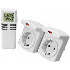
Conrad Energy Count 3000 and ELV Cost Control are wireles 230V electricity consumption measuring plugs Thomas Schulz has cracked the RF protocol of these device back in 2011 on the JeeLabs forum. The signals are FSK encoded and use the 868Mhz band. Thomas was able to receive them with a RFM12B module. Together with a JeeLink V3, it has found popular use with the German home automation software FEHM.

In this post I describe how the RFM69 can take over a task that earlier had to be performed in software.

One of the complications of the protocol is that the preamble of a series of 0x55 is scramble (whitened), and therefore more difficult to recognize. However, after scrambling it is still identical for all packets.

raw data 25 8A F9 59 DA 02 7E 15 ED 67 13 F1 85 D3 AC D2   [payload]   13 E6 84 A8 3B 
descramb 48 BB 55 55 55 55 55 55 55 55 55 55 55 55 55 7E   [payload]   7E 55 55 55 55 
               -------------------------------------- --   ---------   -- -----------
                             preamble                 HDLC  payload  HDLC  postamble

The original Jeelib-based RFM12B programs detection of valid packets was clumsy. Read More

Evaluation noise filtering weak OOK signals – RFM69

As explained in a previous post , noise can spoil the reception of OOK signals from remote sensors. One solution to deal with the noise filtering of spikes in the ON/OFF binary signals is to apply a moving average filter of the last n received samples. When n is odd, the “average” is one if more then half the bits in the filter buffer is one, and otherwise zero. With a filter length of n=3 a single outlier sample will not disturb the intended signal. With a filter length of 5, spikes with a duration of two samples can be handled. Clean signals are as snappy as the where, and timings can be determined to the accuracy of the sample rate.

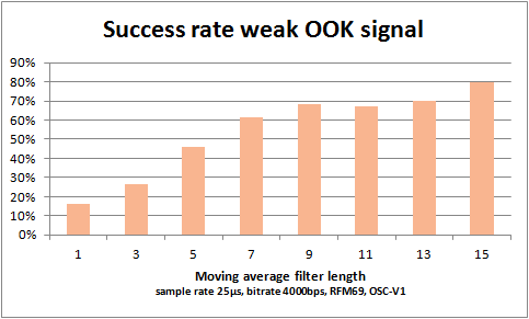
To find the optimal length of the moving average filter, a setup was created with a remote sensor giving a signal that was not received all the time. For each filter length, 100 transmissions where listened to. The graph below shows the success rate as function of the filter length.
433OOK_mov_avg_eval

The binary ON/OFF signal was sampled on the DATA/DIO2 pin of the RFM69 with sample rate 25µs. The bitrate was set to 4000bps. With this setting, the internal sampling rate of the RFM69 is 10µs. This “guarantees” a noisy signal for test purposes. The filter length n=1 is actually unfiltered data at 25µs/sample offered to the decoders. The longest filter length n=15 takes an averaging window of 375µs. This is resiliant to noisy spikes (either ON or OFF) of 7 times the sample rate, thus 175µs. The minimum pulse duration of the received signal, the Oregon Scientific V1 sensor, is about 1100µs, and obviously can stand the long filter periods.

For OOK signals that vary quicker, possibly a shorter filter length should be taken. The shortest pulse durations of OOK sensors and remote controls is around 300µs.

The design of the filter is simply an unbsigned integer, in which the most recent reading (1 or 0) is shifted in from the right. The filter length is enforced by only looking at the least significant n bits. Deciding on the filtered value is a matter of counting the one-bits in the filter.

//moving average buffer, max length = 31!
static uint32_t filter= 0;
static uint8_t avg_len = 7;
static uint32_t sig_mask = (1 << avg_len) - 1;

void receiveOOK() {
    while (....) {
        filter = (filter << 1) | (data_in & 0x01);

        //efficient bit count, from literature
        uint8_t c = 0;
        uint32_t v = filter & sig_mask;
        for (c = 0; v; c++)
        {
          v &= v - 1; // clear the least significant bit set
        }
        uint8_t data_out = (c > (avg_len >> 1)); //bit count moving average

        //decode OOK signal
    }
}
RFM69 AFC failure with OOK

I observed two issues with automatic frequency correction (AFC) and OOK reception:

  • The AFC value does not get cleared by switching to sleep mode and back to receive
  • AFC in continuous OOK mode can yield extreme values, setting the receiver totally off-band.


AFC should not be used in continuous OOK receive mode. I am not sure whether it is designed to work in this mode (I doubt it). When signal is detected by a high RSSI, an controlled AFC may very well be to late for the OOK pulse. But even not enabling AFC in OOK imposses a risk.

When switching between FSK-packet mode for communication with the sensor network, and receiving external OOK signals, the AFC does not get resetted to zero. It can only be done by a HW-reset or power cycle, Or by explicitely clearing the AFC Value:

template< typename SPI >
void RF69A<SPI>::setThd (uint8_t thd) {
    this->writeReg(REG_AFCFEI, (1<<1));
    this->setMode(MODE_SLEEP);
    this->writeReg(REG_OOKFIX, thd);
    chThdSleepMilliseconds(400);
    this->setMode(MODE_RECEIVE);
}

RFM69 OOK signals sampled with RSSI

By polling the RFM69 RSSI register at rates ranging from 25us to 100us, an oscilloscope like picture can be generated for OOK signals.


Read More

RFM69 OOK-mode RSSI behaviour

With the RFM69 in continuous FSK mode, polling the RSSI register at sufficient rate can be used to acquire OOK signals like on oscilloscope. However when doing so with receiver mode set to OOK, it becomes clear that the RSSI register is used internally for some other purposes:


Read More

Unidentified 868MHz OOK signals

In my attempts to receive weather stations on the 868MHz band, without exact knowledge on for example transmission frequencies, I have performed sweeps of frequency range 867.850 – 869.000 MHz in steps of 20kHz. In the loggings I have been looking for periodic signal. Using a histogram of pulse durations, both on and off durations, I was able to recognize signatures of signals. This approach led to the identification of the following signals:

  • Two Alecto WS4000 or similar weather stations.
  • An Oregon Scientific THN128 433MHz, received at 868MHz band.
  • A Philips outdoor temperature sensor for Philips clock radios, also a 433MHz module

Besides those identified signals, I have several unidentified periodic signals, many with a periodicity of around or exact 30 seconds. I have created some signal catalogue for my own reference, but any help on those signals is appreciated. send me a message on info at sevenwatt com.

WH1080 protocol V2 – FSK

The Fine Offset weather station switched over to a new RF transmission protocol somewhere in 2012. While the old protocol was a On-Off-Keying (OOK) protocol, the V2 protocol used Frequency-Shift-Keying (FSK). This is natural transmision mode of the RFM02 transmitters and their RFM01 receivers. The RFM12B modules can also receive the same FSK signals. Most of the reverse engineering happened on the Raspberry Pi forum: WH1080 V2 protocol decoded

This post details on the exact transmission protocol.


Package definition:
[
preample 3 bytes 0xAA    synchron word    payload 10 bytes  postample 11bits zero
0xAA    0xAA    0xAA     0x2D    0xD4     nnnnn---nnnnnnnnn 0x00     0x0
101010101010101010101010 0010110111010100 101.............. 00000000 000
]
repeated six times (identical packages) per transmission every 48 seconds
There is no or hardly any spacing between the packages.
Spacing: to be confirmed.

When using the RFM01 or RFM12B, the preample and synchron word will not be in the received data. The preamble is intended to have the frequency synthesiser locked, while the synchron word serves as detection of the proper message.
Open issue: How can an end-of-transmission be detected? Would VDI turn into zero?
The payload contains to types of messages for FO WH1080, and relatives:

Payload definition:
Weather sensor reading Message Format:
AAAABBBBBBBBCCCCCCCCCCCCDDDDDDDDEEEEEEEEFFFFFFFFGGGGHHHHHHHHHHHHIIIIJJJJKKKKKKKK
0xA4    0xF0    0x27    0x47    0x00    0x00    0x03    0xC6    0x0C    0xFE
10100100111100000010011101000111000000000000000000000011110001100000110011111110


with:
AAAA = 1010    Message type: 0xA: sensor readings
BBBBBBBB       Station ID / rolling code: Changes with battery insertion.
CCCCCCCCCCCC   Temperature*10 in celsius. Binary format MSB is sign
DDDDDDDD       Humidity in %. Binary format 0-100. MSB (bit 7) unused.
EEEEEEEE       Windspeed
FFFFFFFF       Wind gust
GGGG           Unknown
HHHHHHHHHHHH   Rainfall cumulative. Binary format, max = 0x3FF,
IIII           Status bits: MSB b3=low batt indicator.
JJJJ           Wind direction
KKKKKKKK       CRC8 - reverse Dallas One-wire CRC

DCF Time Message Format:
AAAABBBBBBBBCCCCDDEEEEEEFFFFFFFFGGGGGGGGHHHHHHHHIIIJJJJJKKKKKKKKLMMMMMMMNNNNNNNN
Hours Minutes Seconds Year       MonthDay      ?      Checksum
0xB4    0xFA    0x59    0x06    0x42    0x13    0x43    0x02    0x45    0x74

with:
AAAA = 1011    Message type: 0xB: DCF77 time stamp
BBBBBBBB       Station ID / rolling code: Changes with battery insertion.
CCCC           Unknown
DD             Unknown
EEEEEE         Hours, BCD
FFFFFFFF       Minutes, BCD
GGGGGGGG       Seconds, BCD
HHHHHHHH       Year, last two digits, BCD
III            Unknown
JJJJJ          Month number, BCD
KKKKKKKK       Day in month, BCD
L              Unknown status bit
MMMMMMM        Unknown
NNNNNNNN       CRC8 - reverse Dallas One-wire CRC

The DCF code is transmitted five times with 48 second intervals between 3-6 minutes past a new hour. The sensor data transmission stops in the 59th minute. Then there are no transmissions for three minutes, apparently to be noise free to acquire the DCF77 signal. On similar OOK weather stations the DCF77 signal is only transmitted every two hours.

The package format was deduced using a long transmision buffer on a JeeNode with some modificaitons in the RF12 driver.
The payload definitions have been described at those pages:
WH1080 V1 OOK protocol
WH1080 V2 FSK protocol
WH1080 V1 OOK and DCF77 message format

This applies at least to the following (later) models:
Fine Offset WH1080
Alecto WS4000
National Geographic 265, at 916MHz

Receiving 868 and 433MHz weather stations

Receiving 868 and 433MHz weather stations

Using an Arduino, JeeNode, Nodo, or Raspberry Pi with RFM12B, RFM01 or superheterodyne receiver, sensors of popular wireless consumer weather stations can be received. Your own, or your neighbors. This article is dedicted to collecting internet source on RF transmission protocols, as the available information seems to be scattered a lot. Oregon scientifc protocols are readily available. Then there semes to be a whole class of OEM weather stations from China, such as Fine Offset. Some of those modesl are avialable as Maplin, Alecto and more. Personally I started with a superheterodyne receiver at 433MHz, with which I was able to recieve my version-1 protocol Orgeon Scientific THN128 sensor, only in the same room. It did not make the next room. But my main sourceof inspiration was this article: http://www.susa.net/wordpress/2012/08/raspberry-pi-reading-wh1081-weather-sensors-using-an-rfm01-and-rfm12b/
which inspired me to invest in HopeRF modules. After I was able to receive Alecto WS4000 or alike stations (two somewhere in the neighborhood, but not the one I aimed at) with a Raspberry Pi, and very noisy with an Arduino Nano, I decided to invest in JeeNodes. Now my “production receiver will be a Jeenode with on-board RFM12B, or added RFM01. To be decided. My experimatal platform is the Raspberry Pi, as I can code easily very sloppy, use large amounts of memory and do all kinds of checks while still being in time for the next pulse.

The following sites/communities have loads of information on receiving weather stations:
http://www.jeelabs.org
http://nodo-domotica.com
The Nodo community is imho a bit difficult to access, as the major source of documentations is the c-code of a userplugin.

Through the following links RF transmission protocols descriptions can be found:
Oregon scientific:
Detailed description of V1, V2, V3 protocols:
http://wmrx00.sourceforge.net/Arduino/OregonScientific-RF-Protocols.pdf
Decoding of the V2 protocol links to jeenode/arduino/atmel code:
http://jeelabs.net/projects/cafe/wiki/Decoding_the_Oregon_Scientific_V2_protocol