Ford Nugget LINBUS – part 8: LED lighting

The LED lighting in the interior of the Nugget are also connected to the LIN bus. The standard LED option has four different LED strips each controlled by a physical ion/off switch and for all four strips there is a (physical) common up/down dimmer switch. Through the hidden service menu of the touch screen panel an additional LED menu can be added to the touch screen display. On this menu the LED intensity can be controlled like the hardware dimmer switches. Next to that the color tone (warm/cold light) can be controlled, however the standard LED strips are monochrome so it is of little use. On the LIN bus, the messages with ID=0x05 and 0x3B are associated to the LEDs. Looking at ID=0x05 there is one byte, the second byte of 8 that carries the settings information on Intensity and Tone:

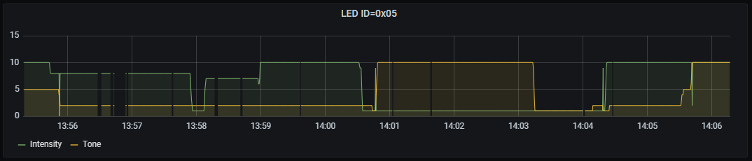
The Intensity and Tone can vary between 1-10. The first byte appears to contain some status bits explained below. The remaining bytes of the 8-byte message seem to always contain zeroes. The other message ID associated to the LED’s seems to replicate this information if the first two bytes but there are small differences:

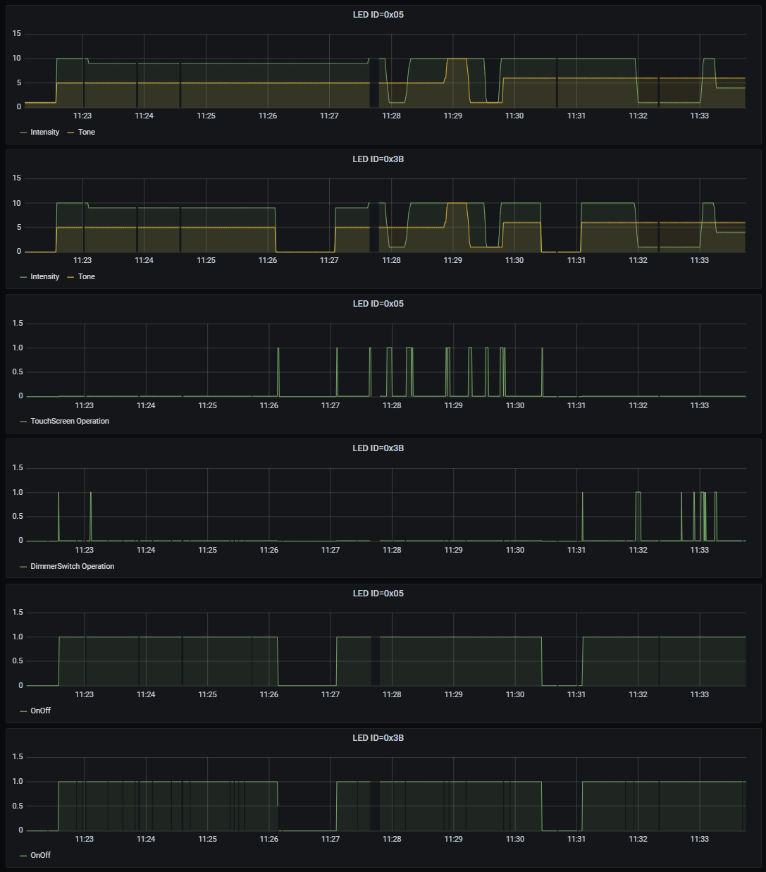
Bit 0 of Byte 0 of this message is zero when the LEDs are disabled or turn-off in the touch screen menu and right after turning on the 12V main switch. See the two bottom traces. When the LEDs are turned off form the touch screen, interestingly the message ID=0x05 still retains the Intensity/Tone settings, while in the 0x3B message those are both set to zero.

Bit 7 of Byte 0 is high when the Intensity or Tone are controlled as can be seen from the two middle traces. The message ID=0x05 has this bit high when it is touchscreen operated. While ID=0x3B has this bit high when it is operated from the physical dimmer buttons.

This last bit may have the purpose of notifying either the touchscreen or the LED controle module that settings of Intensity (and/or Tone) are being changed so that the other party can update the information accordingly. When the Dimmer switch is operated, the LED module sets bit 7 of byte 0 high in the response to a 0x3B header so that the touchscreen can update its Intensity. When the touch screen is operated to either change Intensity and Tone settings or the on/off button on the display is used, it sets this same bit high in the 0x05 message where the touchscreen most likely send both the header and the data part of the actuator-type LIN bus message.

The decoded protocol description is:

--------------------------------------------------------------------------------
LED lighting 1
ID  : 0x05
data: 01 5A 00 00 00 00 00 00
       |  |  |  |  |  |  |  |
      AA  |  |  |  |  |  |  |  = b0: 1 = power on (touchscreen leading)
          |  |  |  |  |  |  |  = b7: 1 = touchscreen operated
         TI  |  |  |  |  |  |  = upper nibble: Color Tone T: 0-10
             |  |  |  |  |  |  = lower nibble: Intensity  I: 0-10
            ??  |  |  |  |  |  = (always 0x00)
               ??  |  |  |  |  = (always 0x00)
                  ??  |  |  |  = (always 0x00)
                     ??  |  |  = (always 0x00)
                        ??  |  = (always 0x00)
                           ??  = (always 0x00)

--------------------------------------------------------------------------------
LED lighting 2
ID  : 0x3B
data: 01 5A 00 00 00 00 00 00
       |  |  |  |  |  |  |  |
      AA  |  |  |  |  |  |  |  = b0: 1 = power on (dimmerswitch leading) 
          |  |  |  |  |  |  |  = b7: 1 = dimmer switch (kitchen side) operated
         TI  |  |  |  |  |  |  = upper nibble: Color Tone T: 0-10
             |  |  |  |  |  |  = lower nibble: Intensity  I: 0-10
            ??  |  |  |  |  |  = (always 0x00)
               ??  |  |  |  |  = (always 0x00)
                  ??  |  |  |  = (always 0x00)
                     ??  |  |  = (always 0x00)
                        ??  |  = (always 0x00)
                           ??  = (always 0x00)

--------------------------------------------------------------------------------

Ford Nugget LINBUS – part 7: Votronic MPPT 440 CI solar charger

The main purpose of examining the LIN bus in the Nugget is to develop a DIY monitoring device and website or app to be keep track of produced solar energy and the state of the batteries. The Votronic MPPT 440 CI has been selected as it supported the so-called CI-bus, which is more or less the same as a LIN bus, at least technically. And although being part 7, it is also the first device that got studied and decoded. A typical graph of Power, Current and Voltage looks like this:

On November 7th, it charged with around 100W. At this day the Nugget was parked in a sunnier location.

The Votronic answers to ID=0x20 on the LIN-bus. The first trace, Power is provided by the Votronics respons. The second and third trace, Current and Voltage are taken form the Hella IBS for reference purposes. The fourth trace is a status byte that I could partially decode. In the dark days and given de bad condition of the batteries, it will not get into the “float” condition so further decoding of the status has to wait until april or may. In those months charge currents above 15A are expected.

The “Power” value takes even 4 bytes of information. The calibration (x/47500) is provisional as charge currents are very low in the winter months. More importantly, it is unclear whether the bytes in the message represent a Power or a Current. Only with higher charge currents and more diverse battery charge states (read voltages during charging) this open question can be answered.

The same applies to the status bytes. In below protocol description some status bits in the byte are identified and the observed correlation or semantics is mentioned. However at least proper “float” conditions need to be observed before more certainty can be gained.

--------------------------------------------------------------------------------
Votronic solar MPP regulator
ID  : 0x20
data: 6B 01 00 00 40
       |  |  |  |  |      
      PL PM PH PX  |           = Power (x / 47500) W - TBD Power or Current?
                  ST           = Charger status 0x40 = offline 
                   |             0x44 = bulk 0x5D = absorb 0x4D = bulk+absorb
                   |           = b0: 1 = high voltage when car engine running (14.7V)
                   |           = b2: 1 = online / or bulk, 0 = offline/sleep
                   |           = b3: 1 = absorb(1)
                   |           = b4: 1 = absorb(2) when car engine on, high voltage 
                   |           = b6: 1 (always)

--------------------------------------------------------------------------------

Finally, I hoped to find also information on the MPPT tracking on the LIN bus. Or Voltage and Current at the solar panel side. This is not contained in the 0x20 message. It may be that the Votronic responds to more ID’s than the one requested by the touch screen. In view of the used ID’s in the Nugget, I don’t expect it. But it remains to be investigated.

Ford Nugget LINBUS – part 6: Dometic PerfectCharge SMP439A

The 230V charger in the nugget is a Dometic PerfectCharge SMP439A. It responds to the IDs 0x18 and 0x19. It only responds to the Leader’s headers when it is connected to the 230V and the main 230V fuse at the side panel below the kitchen is switched on. When i is not connected to 230V, the headers remain unanswered. Both messages are short. The contain some status bytes and a signal that I could not yet fully decode. Details below for further investigations. There is also a charging voltage and current in the data.

--------------------------------------------------------------------------------
Dometic PerfectCharge SMP439A
ID  : 0x18
data: B9 5D 34 00
       |  |  |  |
      AA  |  |  |               = unknown signal. May represent estimated MaxCap
         VL VH  |               = Vcharge (=Vbat) (x/1000 V)
               ??               = (always 0x00)
               
--------------------------------------------------------------------------------
Dometic PerfectCharge SMP439A
ID  :  0x19
data: 23 09
       |  |
      II  |                    = I-charge (x/2 A) in steps of 0.5A             
         AA                    = charger status. No corr. found with I, V, T, Cap
                                 0x00, 0x09, 0x14 observed

--------------------------------------------------------------------------------

The first recorded run is presented below. Typical charge currents are around 5A. In later runs up to 7A has been observed. The Voltage never rises above 14.1V.

Capacity calibration

Two months before the Nugget was connected to the 230V the battery has been drained to near dead conditions. After that the solar panels had been installed and they already partially charged the batteries with a V-bat=12.5. However, the Hella IBS rated the Maximum available capacity at 122Ah. In the third trace it can be seen how the Hella IBS responds to continued charging. First the Available Capacity starts increasing, until it surpasses the maximum configured capacity of 190Ah. From that moment on it decides that the batteries have more capacity than the anticipated 122Ah, and starts correcting the maximum capacity until it reaches the maximum configured capacity. 

From then on the charger continues to put charge in the battery. However, the batteries are not supposed to take more charge than they can hold so the additional energy is clearly dissipated (into heat). consequently the batteries starts to become warmer as can be seen from the fourth trace. Needless to say that the batteries are severely impacted by the almost full discharge condition that they suffered from earlier.

Status information

The status information could not be decoded. One status byte (Ch5) in the graphs has shown three distinct values (0x00, 0x09 and 0x14). In first instance 0x14 seems to correspond with bulk charging and 0x09 with absorb-charging (see third trace below):

However on a later run there are many occasions where it is not charging in Ch5=0x14 and is charging in Ch5=0x09:

The Ch5 value in the third trace has only two discrete values (0x09 and 0x14). Sometimes it looks like it has in-between values, but that is a graphing artifact. Finally there is an unknown time series signal. Only in the very first run it started with values around 50, but ever since it stayed around 183. It may be some estimation of the battery capacity, but that is really a long shot:

Ford Nugget LINBUS – part 5: Eberspacher diesel heater

The Eberspacher diesel heater is associated to message frame ID’s 0x39 and 0x3A. The messages with ID=0x39 contain information on the operation mode such as “circulation” or “heater on” and in a different byte the distinction between “comfort” and “intensive”, as well as the set-point temperature and the actual interior temperature. Responses to message ID=0x3A contain sensoric information on the heater, as well as a seemingly duplicated set point temperature. The following graphs show various traces of the (decoded) temperatures and identification of status bits:

The graph shows two different runs of the heater. The first in comfort mode between 11.00 and 14.30 and the second in intensive mode starting at 17.30. The second trace shows when the heater was turned on. The third trace, value hu07 shows the difference between comfort and intensive. It also shows that the setting is still transmitted when the heater is turned off. The fourth trace does not seem to add information, but in different runs not depicted here it shows different values when the heater is actually switched off when hot air is being produced and when the system is in recirculation mode. The fifth and last trace shows an interesting difference between comfort and intensive operation.  This signal is mostly 0x07, but in comfort mode when the burner (or fan?) is actually running it has the value 0x27.

The currents during operation of the heater are around I=10A when the heater is starting to heat and around I=0.56A when only the fan is running (observed in intensive mode). I assume that the 10 amperes are drawn when the diesle fuel needs to be pre-heated.

Decoding the of the various temperatures was simple enough. Interestingly between the Nuggets interior and outside sensors and the heater sensors the actually translation between byte values and temperature is different Also the interior temperature that is inputted to the heater has a byte value resolution of 0.1 degree while the original source in message ID 0x02 has a resolution of 0.5 degrees. The heater’s measurement of the interior temperature is very close to the Nuggets’interior thermometer, especially when heated. When not in operation it can be clearly seen that those are two different sensors. compere the red and orange line below:

Message 0x39 contains the setpoint of the heater, and message 0x3A has seemingly a copy of this information. However I have observed once that they are not in agreement:

This happened when the heater was changed form intensive operation to circulation. I don’t recall the exact sequence of changes on the touch screen. Possibly I first turned it to circulation and than increased the set point to 20 degree. I may have changed the setpoint back to 19 degree when I turned on the heater again to make differentiated conditions for decoding. The heater itself may not be interested in the setpoint when in circulation mode.

The partly decoded heater frames are summarized below:

--------------------------------------------------------------------------------
Eberspacher diesel heater
ID  : 0x39 
data: FF 02 50 80 02 00 00 80
       |  |  |  |  |  |  |  |
      ??  |  |  |  |  |  |  |  = (always 0xFF)
         AA  |  |  |  |  |  |  = 0x00 = off, 0x02 = heater on, 0x08 = circulation
            TS  |  |  |  |  |  = Setpoint temperature (x/2 - 40 °C)
               TL TH  |  |  |  = Room temperature to heater (x/10 - 50 °C) 
                     ??  |  |  = (always 0x00)
                        ??  |  = (always 0x00)
                           CI  = 0x00 = comfort (or circulation). 0x80 = Intensive

--------------------------------------------------------------------------------
Eberspacher diesel heater
ID  : 0x3A
data: 9A 00 35 36 50 00 50 27
       |  |  |  |  |  |  |  |
      ??  |  |  |  |  |  |  |  = (always 0x9A)
         ??  |  |  |  |  |  |  = (always 0x00)
            TO  |  |  |  |  |  = outlet temperature (x/2 - 40 °C)
               TI  |  |  |  |  = intermediate temperature (x/2 - 40 °C)
                  TS  |  |  |  = setpoint temperature (x/2 - 40 °C)
                     ??  |  |  = (always 0x00)
                        AA  |  = some status, possibly fan related 
                            |    0x00 off
                            |    0x20 during circulation
                            |    0x40 cool-down/fade-out of heater
                            |    0x50 heater on
                           BB  = 0x00=off, 0x02=comfort, 0x27=intensive 

--------------------------------------------------------------------------------

Most literature of the LIN bus assumes that there is a “Leader” on the bus and one or more “Followers”. Typically the Leader sends a header consisting of “Break-Sync-Indentifer” and the Followers respond with 2-8 bytes of data and a checksum. This paradigm works well for sensors which values the Leader likes to know. (See this NXP link for leader/follower terminology). Now on a LIN bus typically there are also actuators, which are also Followers. Actuators need to be provided with data so that they know what to do.

From this perspective the Leader can provide the data of the response part and the Follower listens to this data. From a puristic view one could say that the device that implements the Leader also implements a Follower. The second follower than listens in on the information.

In case of the Eperspacher heater I believe that the message with identifier 0x39 is the Leader’s message of the Touch screen to the heater to provide all the information needed for the operation of the heater. The 0x3A message is a typical sensor type message where the touchscreen sends the message and the heater send the response of its operational conditions. Strangely enough it is hard to find information on this way of operating a LIN bus. I come to this conclusion because there is not other communication on the LIN bus to provide mode and set point to the heater from the touch screen and I also believe there si not other connection between display and heater except for the Lin bus.

Ford Nugget LINBUS – part 4: Coolbox and sensors

The messages related to the coolbox are detected for message ID’s 0x01, 0x02 and 0x04. I associated message ID 0x01 with the Touch screen operating display and in case of the coolbox this message ID contains the setting of the cooling level of the coolbox. Message ID 0x02 and 0x04 may be associated with a nugget electronics box under the kitchen. Both contain temperature sensor information as well as other state information. It is actually a mixed bag. First lets focus on the coolbox:

ID = 0x01 contains the coolbox level  in data byte 1 (second byte) but in its high nibble (actually bit 4 and 5). ID = 0x02, byte 4 contains temperature sensor data and in ID = 0x04 byte 1 contains a bit that is high when the compressor runs (bottom trace). The graph aggregates a couple of values, but actually the yellow line consists of values 0 and 2 (only). Not displayed but actually there is a copy of the temperature sensor in 0x04, byte 4. Due to a imprecise Thermometer it took me a while to figure out the relation to the red signal (byte 4 of 0x02) and the actual temperature. There are actually two possibilities. The value is a measure of the resistance of the NTC or it is already in the temperature domain. When using a more precise thermometer in the above runs and also using some datapoints collected over the weeks before when the fridge was off, using the inboard temperature reading I could make a fit between byte values and observed temperature in the fridge. The relationship was simple and very linear. This discarded the hypothesis that it would be resistance values. 

When reducing the number of decimals in the fitted equation it simply reads y=-x+25 or T=-(B4) + 25. Using this conversion we get this relation between byte 4 value and the coolbox temperature:

Performing some more measurement we can see that the coolbox uses about I=5A when the compressor is running.

Next to the observation that byte 1 (u41 in graph) in message 0x04 contains a bit that indicates the compressor is running, there is a bit that shows the opposite behaviour: byte 3 (u43). Coolbox level in the top right is the decoded byte 1 of 0x01. 

The byte 3 of 0x04 contains some more status bits. Those are related to the ignition state of the car part of the nugget. Bit 2 is indication that the engine is running while bit 0 reflects that the contact of the car is on (0 = on). Byte 0 of 0x04 are also indicating the car contact is on and the engine is running. I expect that 0x04 contains some more information on the electrical pathways in the Nugget, but due to may Camper battery condition I can not test it at the moment.

Finally 0x02 contains the sensor data for the outdoor and indoor temperature sensors as displayed on the touchscreen. And I have found some water tapping related bits in 0x01 and 0x02. Below is the current state of knowledge on those 3 message ID’s:

--------------------------------------------------------------------------------
? Touchscreen central controller ?
ID  : 0x01
data: 00 30 00 00 00 00 00 00
       |  |  |  |  |  |  |  |  
      AA  |  |  |  |  |  |  |  = b0: 0.4-0.5s high when operating display
          |  |  |  |  |  |  |    b1: waterpump 0=off 1=on
         CB  |  |  |  |  |  |  = High nibble (b5,b4): coolbox level setpoint 0-5
            ??  |  |  |  |  |  
               ??  |  |  |  |
                  ??  |  |  |
                     ??  |  |
                        ??  |
                           ??
    
--------------------------------------------------------------------------------
? Central controller (sensors?) ?
ID  : 0x02
data: 5C 5F D7 D7 0B 03 00 00
       |  |  |  |  |  |  |  |  
      TO  |  |  |  |  |  |  |  = T-outside ((120-x)/2 °C)
         TI  |  |  |  |  |  |  = T-inside  ((120-x)/2 °C)
            ??  |  |  |  |  |  
               ??  |  |  |  |
                  CT  |  |  |  = T-coolbox (25-x °C)
                     GF  |  |  = Water level indicators Grey and Fresh water values 0-5
                        HH  |  = 0x40 for 0.4-0.5s when menu operated.
                           AA  = b0: watertap 0=closed 1=open 

--------------------------------------------------------------------------------
? coolbox + car signals ?
ID  : 0x04
data: 00 02 00                   (mostly 3-byte frames)
data: 00 00 00 3B 13 00 00 01    (periodically 8-byte frames)
       |  |  |  |  |  |  |  |
      AA  |  |  |  |  |  |  |  = 0x01 car contact on 0x05 car engine running
         CS  |  |  |  |  |  |  = Coolbox compressor running  0x00 off, 0x02 = on
            ??  |  |  |  |  |  
               BB  |  |  |  |  = normally 0x3B, 0x36 car engine running
                   |  |  |  |    b0: 0 = contact on
                   |  |  |  |    b1: 1 = coolbox compressor runs
                   |  |  |  |    b2: 1 = engine running
                  CT  |  |  |  = Coolbox temperature sensor. same as ID 0x02 CT
                     ??  |  |
                        CC  |  = 0x40 for 0.4-0.5s when heater setpoint changed
                           ??
                   
--------------------------------------------------------------------------------

Ford Nugget LINBUS – part 3: Devices and Hella IBS

The following list contain all observed device ID’s that are addressed on the bus. Several of the device IDs can be attributed to particular equipment or sensors.

ID      Device
0x01    Central Electronics or LCD Display
0x02    Central Electronics or LCD Display
0x04    Unknown
0x05    Unknown
0x06    no response
0x0C    no response
0x17    no response
0x18    Dometic PerfectCharge SMP439A
0x19    Dometic PerfectCharge SMP439A
0x1B    Unknown
0x20    Votronic MPP440CI solar regulator
0x22    Hella IBS
0x25    Hella IBS
0x26    Hella IBS
0x38    no response
0x39    Eberspacher diesel heater
0x3A    Eberspacher diesel heater
0x3B    Unknown

Some of them do never respond. Those are probably provisions that this Ford nugget is not equipped with, such as an electric sliding door step or an airco. Others have never changed a value in the data of the frame.

The Hella Intelligent Battery Sensor LINBUS protocol has been decoded before as mentioned in part 1 of this series.

--------------------------------------------------------------------------------
Hella IBS Current Volt Temperature
ID  : 0x22 
data: AB 84 1E F4 2E 84 7A
       |  |  |  |  |  |  |
      IL IM IH  |  |  |  |     = Ibat (x-2000000)/1000 Ampere, Ibat>0: charge 
               VL VH  |  |     = Vbat x/1000 Volt
                     TT  |     = Tbat x/2-40 °C
                        ??     = 0x7A and 0x7C observed, correlates to unknown6?
                                 0x7C associated to voltage drop to certain point

--------------------------------------------------------------------------------
Hella IBS State of charge, state of health
ID  : 0x25
data: 81 80 E9 B8 BB 00
       |  |  |  |  |  |  
      CC  |  |  |  |  |        = State Of Charge x/2 in Procent
         HH  |  |  |  |        = State Of Health x/2 in Procent
            ??  |  |  |        = unknown4 / correlation to Cap_Available or SOC?
               ??  |  |        = unknown5 / no direkt link to unkown 4?
                  ?L ?L        = unknown6 / corelation to Cap_Available or SOC?

--------------------------------------------------------------------------------
Hella IBS Capacity
ID  : 0x26 
data: C5 04 CD 04 5F FF
       |  |  |  |  |  |  
      ML MH  |  |  |  |        = Max seen Capacity x/10 Ah (=SOH ?)
            AL AH  |  |        = Available Capacity x/10 Ah (=SOC)
                  CC  |        = Configured Capacity
                     ??        = CalibByte, maybe filled with stuffing bits?
                      |        = b0: CalibrationDone flag, 1=ok, 0=uncalibrated

--------------------------------------------------------------------------------

The Hella IBS can respond to requests on several other IDs, such as 0x21, 0x23 and 0x24. The central electronic module of the Nugget however only requests for the above described three frame types.

Ford Nugget LINBUS – part 2: Hardware and IDE

An Heltec ESP32 module with OLED screen was chosen for the ease of having a (tiny) OLED screen besides the standard capabilities of Wifi and Bluetooth connection and a USB interface for easy programming. An Heltec 32 Wifi Lora V3 was used. In this project I don’t expect to use the Lora radio. 

To interface the 3.3V based microcontroller to the harsh +11V to +16V car environment, a dedicated LINBUS interface using the TJA1021 chip was selected. This takes care of all the level shifting between the voltages and splits the one-wire LIN bus into a two-wire standard serial interface TX/RX. The LIN-BUS<->UART board can be found on amazon or from Chinese webshops.


Currently a standard DC jack 5.5/21.mm is connected to the the LIN-interface voor the power supply and the blue LIN bus wire connects to an available LIN bus spade connector behind the campervan-side batteries of the Nugget. The ESP32 is powered through a USB cable. Eventually when making a more permanent design it can powered form the car battery side with an additional DC/DC convertor.


As Software Development Environment I use Visual Studio Code and the PlatformIO plugins. Within PlatformIO I make use of the Arduino framework for ESP32 and installed the ESP32 and Heltec libraries. The latter for OLED support. The code will eventually end up at github. 

An introduction to coding and programming the ESP32 is beyond the scope of this post. Many good tutorials can be found, for example those:

PlatformIO tutorials or Random Nerds Tutorials

To interface with the LIN bus I forked two repositories of Mestrode. The first is a library to drive the dedicated functions of the TJA1021, and the second is the generic implementation of the LIN bus protocol using a serial interface of the ESP32. Both I had to fork as I needed to extend them. The transceiver library was using hard-coded TX/RX pins and for the Heltec board those pins were occupied by other functions. And for the interface library there was no spy-mode reading function implemented. I need to listen-only to the bus, while it is not in sleep mode. A new frame can come at any moment.

https://github.com/SevenW/Lin-Transceiver-Library

https://github.com/SevenW/Lin-Interface-Library

The actual code is not pushed to github yet.

Ford Nugget LINBUS – part 1: A first look

connecting the oscilloscope

After installing solar panels on the roof of the campervan I wanted to see whether the solar voltage regulator was providing electrical potential and current data at the solar panel and battery side. The Votronic MMP solar regulator is connected to the LIN bus of the campervan. So I build a “sniffer” for the LIN bus and did some programming on an ESP32 board. To get it all working the oscilloscope came in handy. For example to figure out the baud rate of the LIN-bus.

LinBus trace of 1000ms showing a repeating pattern of approximately 360ms

The baud rate appears to be 19200 and it appears to be a repeating pattern every 360ms. Zooming in on the data reveals that

  • There is a single “spike” of about 3ms
  • After 47ms it is followed by a train of 10 frames
  • After 82ms it is followed by a second train of  frames
  • Finally after 47ms the single spike is detected again.

Individual frames

The short frames (called spikes before) are requests from the master on the LIN bus that remain unanswered, because the device is offline or just not build into the campervan. They contain typically the byte sequence 00 55 xx where xx = the Protected ID:

Master request that remains unanswered to Protected ID = 0x5B

The frame always start at nice 10ms time slots,. An example of a regular frame comes form the campervan living part batteries intelligent battery sensor:

Hella IBS frame PID = 0x25 (State of Charge SoC)

The Hella IBS sensor LIN bus protocol is well documented in those github repositories:

https://github.com/frankschoeniger/LIN_Interface

https://github.com/mestrode/IBS-Sensor-Library

Frame identity

Finally, the complete overview of the frames with Protected and normal ID’s:

start time
/ ms
PID
(hex)
ID
(hex)
comment
0 (=360)C101
104202
20C404
308505
40FB3B
500C06no response
609717no response
70D818no response
809919no response
1305B1Bisolated spike, no response
180C101called a second time
1904202called a second time
2002020
210E222Hella IBS
2202525Hella IBS
230A626Hella IBS
2407838no response
2503939
260BA3A
2704C0Cno response

Several Frame IDs do not have a response. Device ID 01 and 02 are called twice in a cycle and three of the ID’s are known to be from the Hella IBS and for the better part the data is decoded. More posts will appear among others on the LINBUS listener based on an ESP32 and decoding of the frames of some of the connected devices.

Receive Buienradar BR-1800 weather station on RFM69 and Lora modules

My local sailing club has a Buienradar BR-1800 weather station with its indoor unit in the start/finish venue. There it is inaccessible to the sailors. I have some past experience in weather stations. I was the first to receive FSK signals from a WH1080 weather station. Before that time OOK was the modulation of choice. As sailor I actually want to be able to read the local wind and direction, preferable also from home. So I set out to make this weather station internet connected.

I started googling on to my surprise I found only questions of people who wanted to connect this to for example Domoticz but no easy solutions that I could reuse. Later I learned that there is an implementation which is copied by one or two others. That was after the fact!. Googling on reverse engineering or rf protocol for the BR-1800 I found two useful pieces of information. The first indicated that the BR-1800 is a Fine Offset WH-2300 and it had two spreadsheets with the RF protocol (RF properties and packet format). Searching of WH-2300 did not result in more knowledge. The second interesting information was a picture of the internal PCB that showed a footprint of the radio module used. I quickly recognized that as a HopeRF RFM22.  


The FSK signals are compatible across a range of HopeRF radio’s. Together with the protocol spreadsheet there was enough information to get me started. I pulled a STM32-based Jeenode Zero with RFM69 radio form the box and set up a PlatformIO environment using the jeelabs/Jeeh library as a lib_deps. With reusing some code and register settings form my earlier WH1080 work I was able to quickly make a receiver implementation.

So I went to the sailing club (sailed a bit first), opened my laptop and after a few minutes I had received the raw data of several packets. Back home! After studying a bit and comparing to the expected protocol I noticed that the payload was too short and I actually recognized it. I hooked up the WH1080 packet decoder and indeed, WH1080 / WS400 signals. There is another station at the club, maybe on a boat. But I should have received Buienradar BR-1800 signals as well. Same frequency and bitrate.

The next day I went back to the club and decided to inspect the indoor unit. It had no reception of the outdoor unit. So I took a long ladder and removed the outdoor unit and brought it home. checking the batteries learned that the rechargeable NiM-hydrides were completely flat. So much for a solar recharging system. After fixing this and hooking up the Jeenode Zero again I started receiving the signals. After tweaking a bit with preamble and syncword detection settings I was receiving over 80% of the transmitted packages. Next step: Decoding.

As the format is clearly related to the WH-1080 and using the rf protocol spreadsheet it was not too difficult to write the decoding algorithm. The CRC turned out to be the same as for the WH-1080. By now I had realized that this outdoor unit “architecture” is actually better known as WH24. There are some FCC records for clearance in the USA. Searching on WH24 I finally found  source code in Benjamin Larsson repository. In this file details of the protocol and decoding can be found. I used this to “compare notes” and copied code to derive the UV-index. In the end it turns out that the BR-1800 uses a different UV-index scale. 

After hooking up the Jeenode Zero with RFM69 I started to receive some packets. With some tuning of preamble and syncword detection I receive over 80% of the transmissions. At this point in time I have a working implementation. 

RF69 #17: 24 3c ce 62 19 63 0f 03 00 02 00 00 00 00 00 a9 c9
r 116 l 2 a-1525

checksum  ok crc  ok
ID: 3C, T=13.7°C, relH=99%, Wvel=2.1m/s, Wmax=3.4m/s, Wdir=206°, Rain=0.6mm, UV=0, UVindex=0, Light=0.0, battery ok

The final goal is to connect the Buienradar BR-1800 with wifi to the internet. ESP32 is a very useful solutions. They are available with HopeRF (RFM95/RFM96) and SemTech (SX1276/SX1278) Lora modules. So would a Lora module be able to receive the FSK modulated signals. The answer is yes which I will explain in a next post.

Source code will become available on github/sevenw after finishing the project and some cleanup.


Innr SmartPlug for Philips Hue – part 2

Disclaimer

Do not work on the SmartPlug while powered with 230V. The author accepts no responsibility or liability for any adverse effects. This includes but is not limited to potential damage of the device itself, other equipment or personal harm, injury or dead. Working on electrical mains appliances can be dangerous. 230V is dangerous. If you decide to open such a device and work on it, never plug it into mains, until the device is closed again. If you do not feel comfortable with this, or want to experiment while powered with 230V: Do not proceed!

Wiring-up

To program the smartplug, a few wires have to be connected. Only three wires need to be soldered to the JN5168 module. GND and +5V can be taken from the main PCB. Remember the disclaimer. Never work on the smartplug when it is connected to a 230V socket! The following diagrams show how to connect a USB-serial dongle to the smartplug.

Read More