RFM69 OOK – DAGC, Sensitivity Boost and Modulation index

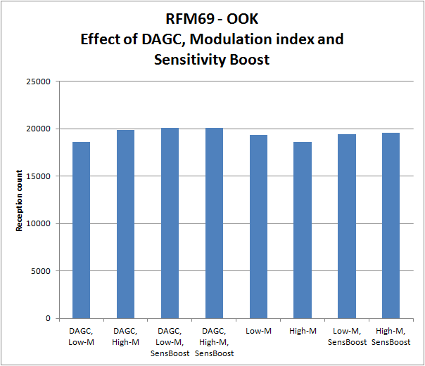
As a final step in exploring the optimal settings for receiving “foreign” OOK signals with the RFM69, the settings for DAGC, Sensitivity Boost and the effect of the Modulation index are explored. The modulation index is actually a FSK aspect, and no effect should be expected for OOK. However, as it can be programmed to High or Low, it is included in the exploration.

Foreign OOK refers to signals that are not natively produced by an RFM69, but are originating form various sensors or remote controls.

From the first results, it can be concluded that Sensitivity Boost has a clear advantage, and also DAGC enabled helps in icreasing sesnitivity:
RFM69SpecialModeHisto
Read More

RFM69 – Energy Count 3000 / ELV Cost Control

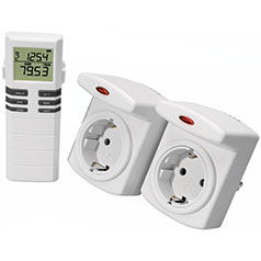
Conrad Energy Count 3000 and ELV Cost Control are wireles 230V electricity consumption measuring plugs Thomas Schulz has cracked the RF protocol of these device back in 2011 on the JeeLabs forum. The signals are FSK encoded and use the 868Mhz band. Thomas was able to receive them with a RFM12B module. Together with a JeeLink V3, it has found popular use with the German home automation software FEHM.

In this post I describe how the RFM69 can take over a task that earlier had to be performed in software.

One of the complications of the protocol is that the preamble of a series of 0x55 is scramble (whitened), and therefore more difficult to recognize. However, after scrambling it is still identical for all packets.

raw data 25 8A F9 59 DA 02 7E 15 ED 67 13 F1 85 D3 AC D2   [payload]   13 E6 84 A8 3B 
descramb 48 BB 55 55 55 55 55 55 55 55 55 55 55 55 55 7E   [payload]   7E 55 55 55 55 
               -------------------------------------- --   ---------   -- -----------
                             preamble                 HDLC  payload  HDLC  postamble

The original Jeelib-based RFM12B programs detection of valid packets was clumsy. Read More

RFM69 OOK compare antenna’s

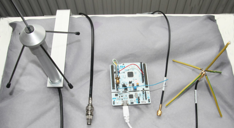
The antenna design of a module like the RFM69 is important for the sensitivity to sognal and noise. Also antenna positioning is important. Putting an Nucleo STM32 with RFM69CW very close to a PC will result in a increase of several dBm’s in noise floor.

Gain 7 dB sensitivity with JeeNodes

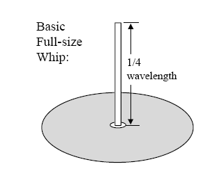
The basic antenna design commonly used is a quarter wavelength wire antenna with ground plane.
quarterwavelengthantenna
From this informative paper from HopeRF, the manufacturer of the RFM69. Such an antenna has a 1/4 wavelength monopole, and a ground plane that serves to reflect (mirror) the wire so that one gets a half-wavelength dipole effect.

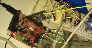
The 86mm wire (at 868MHz) connected to small JeeNode like devices is actually not having much of a ground plane. So this can probably be improved. There are very nice commercial designs for this at 868MHz and 433MHz. A.o from Conrad. So lets putthree 1/4 wavelength antenna’s to the test. The wire is compared to a home build and a commercial 1/4-wavelength with groundplane antenna. (See picture above this article, the blue wire crossing the Nucleo is the wire-antenna). Read More

RFM69 OOK RSSI and optimal bitrate

RFM69 OOK RSSI and optimal bitrate settings are key for proper reception and decoding of “foreign” OOK signals for example form remote controls as FS20, or wireless sensor such as Oregon scientific whether stations. In an earlier post, already some strange behavior of RSSI has been presented. A FS20 RC signal is recorded with 3 different bitrate settings in continuous OOK mode:

At high bitrates, the RSSI signal is much noisier. At 3000bps, the RSSI signal is hardly usable, although the internal bitslicer still can decode the signal, which has bit durations of 400 and 600us. So a too high bitrate will only lead excess noise.

From the 3000bps it can be seen that the RSSI signal is sampled with about 625us intervals. According to the datasheet, the RSSI sample duration depends on the duration of a bit:

t-rssi = 2 * t-bit

So for 3000bps, t-bit=333us, so t-rssi = 666us.
For 32768bps, the t-rssi=61us. As the RSSI signal is recorded with 25us intervals, most of the time two or three adjacent samples will have the same RSSI value.

In an earlier post, it was explained that the internal bitslicer can slice at 1/25 of the bitrate. The fastest signals we want to see have bit duration (ON-time or OFF-time) of 200us (Some Oregon Scientific sensors). So then a low bitrate setting of around 1000bps will do?

From further looking into exact timings or received signals, it appears that this is not true. When looking at a histogram of FS20 signals recorded with 2000bps, it can be seen that distributions of the 400us and 600us signals start overlapping. Also, the OFF-signals can be biased to shorter or longer durations, depending on the choice of OOK-PEAK or OOK-FIXED mode. As a result, the signal cannot be reliable decoded.
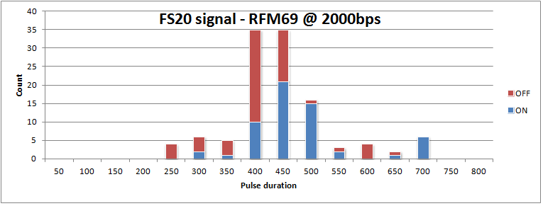
FS20 histo 2000bps

Now this is a bit messy. An ideal signal has both ON and OFF pulses taking either 400 or 600us:
FS20bit
Deciding whether a bit is a zero or one, should simply testing whther the pusle duration is longer or shorter than 500us. Clearly that does not work. Also note it is an odd signal. It has many zero-bits, and only 11 one-bits.

When moving to a higher bitrate (32768bps), the variation on the bit-timing is greatly reduced, and it also appears that the timing is hardly dependent on the OOK-PEAK or OOK-FIX setting.
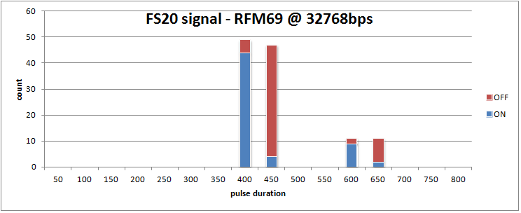
FS20 histo 32768bps

In conclusion, the bitrate should be high enough for reliable bit timings, but not higher then needed, as a lower bitrate means a better noise filtering.
Picos ARM – LPC8xx fun with Jeelabs on Windows

Picos ARM is a series of articles on this blog bringing the new LPC810 Jeelabs.org RFM69 activites described in the JeeBook to the Windows PC. For those who appreciate working with a comfortable full-blown IDE in stead of the Raspberry Pi command lines to build and debug stuff.

The series cover by now:

  1. Setting up an Eclipse IDE for LPC8xx projects in windows
  2. Flashing the firmware to the LPC8xx
  3. Setup of On-Chip Debugging in Eclipse IDE
  4. Connecting the Nucleo STLINK-V2-1 SWD debugger interface to the LPC810

Some Eclipse CDT Plug-ins have been developed to make setup and use of Eclipse IDE easier for the LPC8xx JeeBook type of projects. More will follow soon on easier setup of debugging facilities.

Maple / Olimexino STM32 datalogger for JeeNode network

I have been looking into autonomous persistent dataloggers for a JeeNode based sensor network. The requirements include a Real Time Clock, SD-card storage and battery backup operation. the performance of a standard Arduino / JeeNode based solution was a bit risky, in view of the SD-card operation. Maybe libraries have improved by now, but during SD-card operations, interrupts may be blocked for maybe over a tenth of a second, and that can lead to missing messages from the wireless RFM12B sensor network that I want to collect data from. I considered small ARM-soc computers, like the RaspberryPi. This could also be interfaced with a RFM12B module. It has sufficient processing power, but for me there were two downsides: 1. It consumes 2.5W, so there are higher demands on battery backup. 2. Sometimes it requires maintenance, and may require a reboot once in a while. I just do not want to miss data. So I started looking into more powerfull Arduino-like solutions, and stumbled into a Maple (leaflabs) clone.

2013-11-18 22.04.47

The Olimexino-STM32 is a very interesting board to build a SD-card datalogger on. It has the SD-card slot on board, next to the possibility to feed the circuit with a LIPO battery, which automatically takes over when the USB-bus power supply stops. The board contains a LIPO charger and there is a integrated RTC which can be tuned to drift only 10 seconds per year.

Given the power supply and charger options this board is ideal for a datalogger that should work 24/7 365 days per year. Besides power outages, it also allow for maintenance activities on the server collection all data. When power gets disconnected, it can proceed for about 24 hours on the 1400mAh LIPO battery I connected to it, and when power is up again, it recharges the LIPO cell.

I use a 2GB micro-SD-card (yes, the smallest I had). With my current data inflow, it can buffer data for over a year. The power consumption is about 0.5W from memory. (TODO: measure it again).

To the board I connected a RFM12B 868MHz RF module to communicate with standard JeeNodes. This module is soldered to a RFM12B carrier board obtained from the JeeShop. It provides a pinout compatible with arduino shield connectors, which happen also to be implemented on the STM32 board. This results in very clean wiring.

The Maple-clone is a 3.3V circuit, as well as the RFM12B, so I could leave out the voltage conversion stuff from the board.

At reasonable low cost of around 40 euro’s this datalogger could be build.

  • Olimexino-STM32 E.19.95
  • Lipo 1400mAH (Olimex) E.5.95
  • RFM12B (JeeLabs) E.6.00
  • RFM12B board (JeeLabs) E.3.50
  • box E.3.00

Jeenode RFM12B configuration commands

The following table shows the differences in intialisations of the RFM12B for the JeeNode applicaiton to receiver weather station data from both FSK and OOK stations, and send it to the JeeNode home sensor network, and eventually to HouseMon:

JeeLib nativeWH1080 FSKJeeLib OOKJeelib native remarkWH1080 FSK RemarkJeeLib OOK
0x82050x820Ddisable some circuitsdisable some circuits
0x80E70x80E7 868 Mhz, enable tx+rxidenticaldisable TX and RX buf
0xA6400xA67C0xA68Afrequency
0xC6130xC6130xC691bitrateN/A ?
0x94A20x94A00x9489134kHz, -0dBm, 91dBm 134kHz, -0dB, 103dBm200khz, -6db, 97dbm
0xC2AC0xC220datafilter = digitaldatafilter = OOK
0xCA830xCA830xCA00identicalFIFO disabled
0xCEnn0xCED4group IDgroupID=0xD4!
0xC4830xC49F0xC473AFC auto, free, DQD4AFC manual slow +-16 DQD2AFC @PWR, auto, +-4 DQD4
0x9850
0xCC770xCC670xCC67PLL don't carePLL don't care
0xE0000xE105wakeup timerdon't care
0xC8000xC80E0xC800disable low duty cycle
0xC0490xC0060xC040clock out, low batt leveldon't caredon't care
0XB8000XB800clear transmit bufferclear transmit buffer
0x82DD0x82DD0x82C0enable relevant circuitsidenticalenab receiver, baseband

taking a look at the differences between the native-FSK and WH1080-foreign-FSK, there seem to be some obvious required differences, but also some differences that may not matter that much. For example the auto frequency control (AFC) settings, auto-mode, unrestricted, versus manual, slow, restricted to +/-16steps may not a big deal. So I tested this by making a sketch that receives foreign-FSK, and as soon as a signal is received, it programs the RFM12B to native mode and transmits the package into the sensor network. I extended the RF12 driver with functions below, which speak for themselves. The minimal set of changes can be seen in the following functions:

void configureWH1080 () {
    rf12_setGroup(0xD4);
    rf12_setBitrate(0x13);          // 17.24 kbps
    rf12_setFrequency(0x67C);       // 868.300 MHz
    rf12_setFixedLength(LEN_MAX);   // receive fixed number of bytes
}

void deconfigureWH1080 () {
    rf12_setGroup(GROUP_ID);
    rf12_setBitrate(0x06);          // 49.2 kbps
    rf12_setFrequency(0x640);       // 868.000MHz
    rf12_setFixedLength(0);         // number of bytes to be received in packet header
}

This approach avoids using the slightly costly rf12_initialize() funnction which reprograms the SPI bus and resets the RFM12B.

If you made it to here, but think what is this all about. See this:

Decoding the Oregon Scientific V2 protocol
Receiving OOKASK with a modified RFM12B
FSK 868MHz weather stations on JeeNode
WH1080 protocol V2 – FSK