Disclaimer
Do not work on the SmartPlug while powered with 230V. The author accepts no responsibility or liability for any adverse effects. This includes but is not limited to potential damage of the device itself, other equipment or personal harm, injury or dead. Working on electrical mains appliances can be dangerous. 230V is dangerous. If you decide to open such a device and work on it, never plug it into mains, until the device is closed again. If you do not feel comfortable with this, or want to experiment while powered with 230V: Do not proceed!
Wiring-up
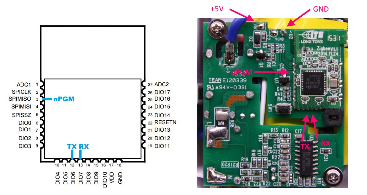
To program the smartplug, a few wires have to be connected. Only three wires need to be soldered to the JN5168 module. GND and +5V can be taken from the main PCB. Remember the disclaimer. Never work on the smartplug when it is connected to a 230V socket! The following diagrams show how to connect a USB-serial dongle to the smartplug.
The USB-serial interface can usually provide the +5V. I do not advice to power it with 3.3V.
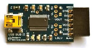 I used a USB-BUB II, which is a popular USB-FTDI-serial interface that is often used, for example for classic JeeNodes. The six-pin header I use has this layout, providing TX,RX,+5V and GND).
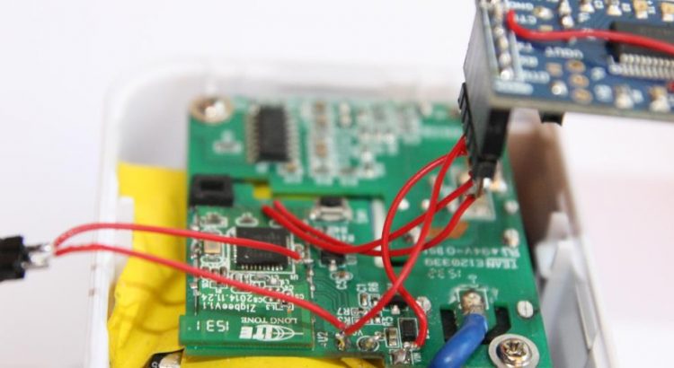
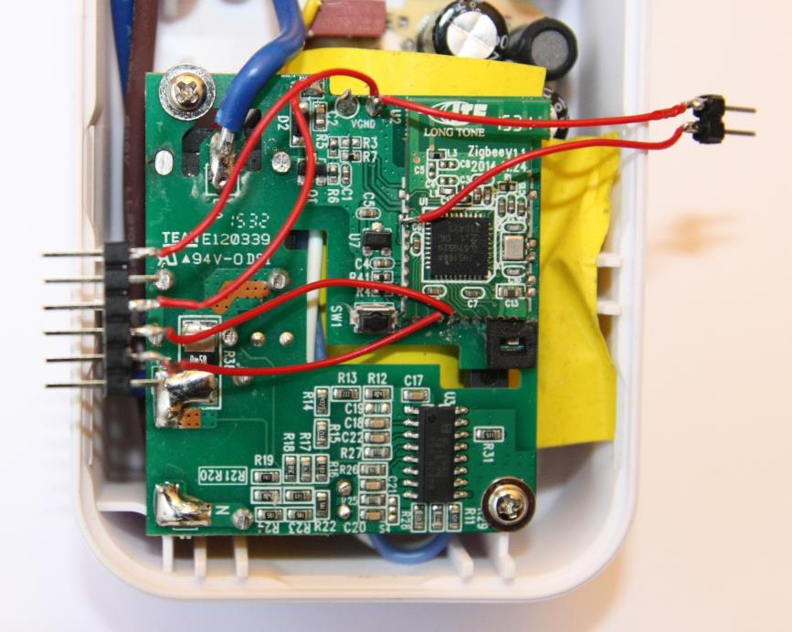
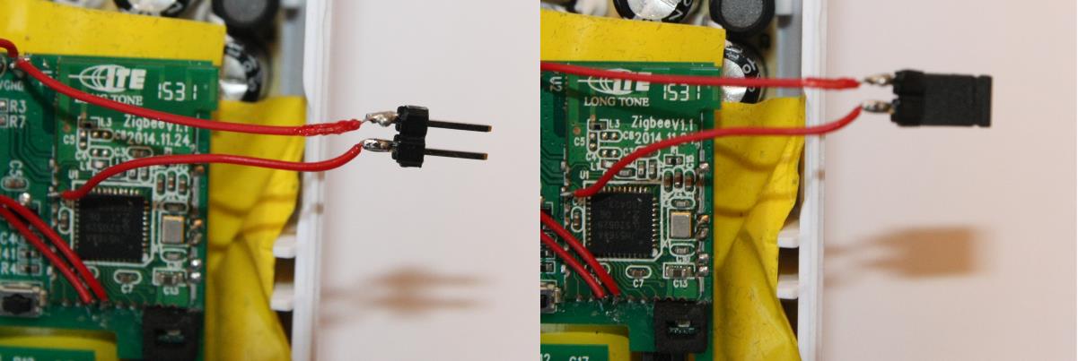
As the usb-serial adapter is chosen, a 6-pin header connector can be soldered to the Smartplug. The picture below shows the result:
To program, pin 3 (DO1/SPIMISO) of the module has to be pulled to ground. For this I soldered a two-pin header with the SPIMISO (nPGM) and GND. I use a jumper-bridge from an old PC to short circuit those pins. I do not bother to connect the nRESET. To bring it in bootloader (program) mode, just place the jumper, and then (re-)power the circuit by unplug/plug the FTDI adapter into the USB port.
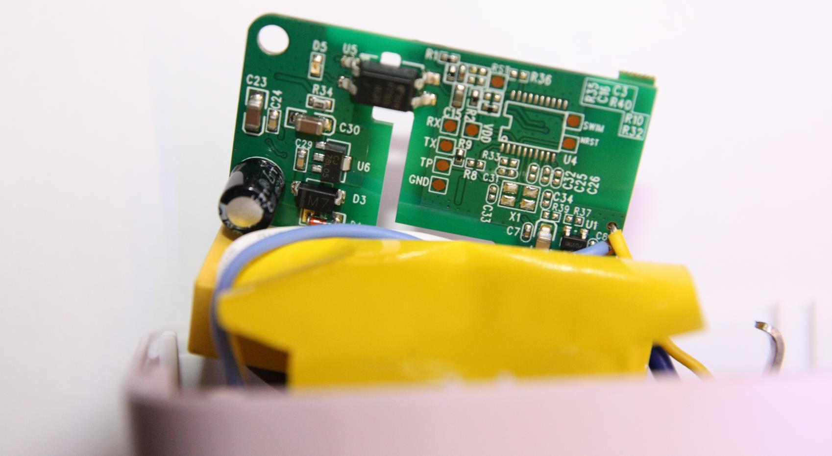 If you don’t feel comfortable soldering to the tiny castellated pins of the JN5168 module, you can solder to soldering-pad areas at the back-side of the main PCB. The pads labelled TX and RX are obvious. pad TP = nPGM (SPIMISO). GND can be taken from here as well. I did not check whether VDD is +3.3V or +5V. So be careful. Better take it from the indicated contacts at the front side of the PCB. I you want to wire nRESET, take the RST pad near R36. Not the other NRST pad.
Now we are all set to go to the software side of the story.
Activate bootloader
As many MCU’s, the JN5168 is designed to be able to protect its firmware. The device can be programmed such that the firmware image can’t be read back, or even that it can’t be reprogrammed. so the first thing to test is can we actually enter the bootloader. Peeveeone described in this post how to use a stand-alone flash programmer. In this post he describes how to setup the JN5168 beyond studio eclipse environment. In this eclipse based environment, a flash utility is included. This is what I use.
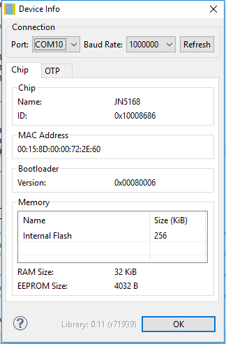 Now lets hook up. In the Eclipse main menu bar I select “Devices” and then “Device Info”. This gave me the following:
This means that the bootloader mode is activated and that I actually can read the content. As I next step, using “Devices -> Read Device” I made a backup copy of the original firmware image and the EPROM content. Then I tried flashing one of the pre-build firmware images. I had a few of my own by then, build following the instructions of peeveeone. In then I enable debugging output to the serial port, so I could see that the functioned as expected without having to worry about the all of the proper connection. The result up-and-running.
The Innr SmartPlug can be reprogrammed!
ZLL/Hue firmware for the Innr SmartPlug
The next step is to write new firmware for the SmartPlug. Starting point is the ZLL Lights github repository of peeveeone. This is based on the NXP application note JN-AN-1171. Peeveeone has build custom firmware for ColorLight and DimmableLight. The Zigbee ZLL standard specifies more types of lights and the best match is OnOffPlug. So first I took this from the sample code of JN-AN1171, and added the support for the OnOff devices to a clone of the github repository. It required some restructuring of the MakeFile and more configurations are added to the Beyond Studio eclipse IDE. To support the Smartplug hardware, A DriverBulb file was added that uses the correct DIO port to control the relay. The App_Light_OnOffPlug.c and DriverBulb_InnrSmartPlug.c where extended with support for the LED and the magnetic switch and manual button. The resulting firmware images can be downloaded from here:
Innr SmartPlug on Philips Hue as OnOffPlug
Innr SmartPlug on Philips Hue as OnOffLight
In the next part of this series the exact functionality of LED and buttons is explained. As well as some considerations on the joining process which is not always easy. I made some improvements to make the process more robust.
Did you get any further with this project? 🙂
Is de next part coming along? Curious to see how a OnOff plug works inside the Hue system
Wow, that is really interesting. Reading your article I ordered a SP110.My hope is that I can use the plug to “HUEify” an ceiling lamp…