The antenna design of a module like the RFM69 is important for the sensitivity to sognal and noise. Also antenna positioning is important. Putting an Nucleo STM32 with RFM69CW very close to a PC will result in a increase of several dBm’s in noise floor.
Gain 7 dB sensitivity with JeeNodes
The basic antenna design commonly used is a quarter wavelength wire antenna with ground plane.
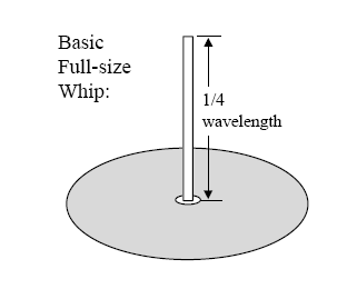
From this informative paper from HopeRF, the manufacturer of the RFM69. Such an antenna has a 1/4 wavelength monopole, and a ground plane that serves to reflect (mirror) the wire so that one gets a half-wavelength dipole effect.
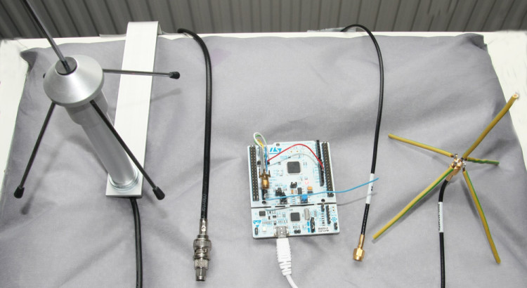
The 86mm wire (at 868MHz) connected to small JeeNode like devices is actually not having much of a ground plane. So this can probably be improved. There are very nice commercial designs for this at 868MHz and 433MHz. A.o from Conrad. So lets putthree 1/4 wavelength antenna’s to the test. The wire is compared to a home build and a commercial 1/4-wavelength with groundplane antenna. (See picture above this article, the blue wire crossing the Nucleo is the wire-antenna).
The resulting noise and signal levels are printed in RawRSSI, which can be converted to decibells:
RSSI (in dBm) = (RawRSSI – 256) / 2
As explained in the previous post, the numbers in brackets are the RawRSSI values during OFF and ON, so
(RawRSSI_OFF/RawRSSI_ON)
Wire antenna
       40622  15     1 FS20  88400031214C (55/79)

       40683      61 2 FS20  88400031214C (57/82)

       40745      62 3 FS20  88400031214C (58/84)
45816 5 1 FS20 88400031214C (59/84)
45877 61 2 FS20 88400031214C (61/90)
45939 62 3 FS20 88400031214C (59/89)
RSSI: 59(v 13-s 4-m126) THD:fix/peak/maxp:71/69/114
Home build
       13794   5     1 FS20  88400031214C (50/85)

       13855      61 2 FS20  88400031214C (51/82)

       13917      62 3 FS20  88400031214C (50/76)
18987 5 1 FS20 88400031214C (49/81)
19048 61 2 FS20 88400031214C (47/82)
19110 62 3 FS20 88400031214C (48/82)
RSSI: 50(v 44-s 7-m127) THD:fix/peak/maxp:65/65/115
Conrad
       21946   5     1 FS20  88400031214C (46/99)

       22007      61 2 FS20  88400031214C (48/97)

       22069      62 3 FS20  88400031214C (48/97)
27140 5 1 FS20 88400031214C (46/96)
27202 62 2 FS20 88400031214C (46/97)
27264 62 3 FS20 88400031214C (47/97)
RSSI: 48(v 40-s 7-m126) THD:fix/peak/maxp:65/65/114
What can be seen is that the noise floor drops from ~59 to ~49 to ~47 for the three receivers (-98.5dB, -103.5dB, -104.5dB).
The noise floor drops by 6 dB with the best antenna.
This gains is impressive and enables the reception of much weaker signals. The transmit-ON level varies a lot more. As the height of the antenna’s above the working surface differed somewhat, those figures are less trustworthy. In fact further experiments showed that with careful antenna positioning signal-ON levels are comparable over antenna design, while noise levels (signal-OFF) are always in the range of the reported values above.
Finally it is good to move the antenna away from the microcontroller or microcomputer used. Moving away the Nucleo STM32 80cm while keeping the Conrad antenna at the same position
Conrad, Nucleo 80cm away
       30893   5     1 FS20  88400031214C (45/98)

       30954      61 2 FS20  88400031214C (44/94)

       31016      62 3 FS20  88400031214C (44/91)
36086 5 1 FS20 88400031214C (46/92)
36147 61 2 FS20 88400031214C (47/93)
36209 62 3 FS20 88400031214C (44/92)
RSSI: 46(v 40-s 7-m134) THD:fix/peak/maxp:61/61/122
The noise floor is now around 45 (=100.5dB), an gain of 7dB!
How about some shielding of the nucleo board
Would you mind posting the names/models of the commercial antennas you tested? We would be grateful. 🙂
Aurel Ground plane 868 650200599, can be obtained from Conrad in Europe.
See http://www.aurelwireless.com/rf-wireless-antennas/